Clutch device and steering device

A technology of clutch device and steering mechanism, which is applied to clutches, mechanically driven clutches, magnetically driven clutches, etc., to achieve the effect of improving steering control feeling

Inactive Publication Date: 2015-04-08
TOYOTA JIDOSHA KK
View PDF5 Cites 2 Cited by
  • Summary
  • Abstract
  • Description
  • Claims
  • Application Information

AI Technical Summary

Problems solved by technology

[0005] However, in the steering device described in Patent Document 1, even when the lock portion is released, the steering wheel and the tires are connected via the planetary gear clutch, and the input from the road surface is transmitted to the steering wheel.
So there is room for improvement in the feel when turning

Method used


Image

  • Clutch device and steering device
  • Clutch device and steering device
  • Clutch device and steering device

Examples


no. 1 Embodiment approach

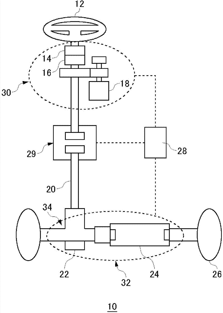
[0030] figure 1 It is a schematic diagram showing the schematic configuration of the vehicle steering device according to the first embodiment. The vehicle steering device 10 includes a steering wheel 12 , a steering angle sensor 14 , a torque sensor 16 , a steering reaction motor 18 , an intermediate shaft 20 , a steering angle sensor 22 , a steering motor 24 , tires 26 , an ECU 28 , and a clutch device 29 .

[0031] The steering actuator 30 is composed of a steering angle sensor 14 , a torque sensor 16 , and a steering reaction force motor 18 . In addition, the steering actuator 32 is constituted by the steering angle sensor 22 and the steering motor 24 . The ECU 28 controls the steering reaction motor 18 and the steering motor 24 based on various sensor information of the steering actuator 30 and the steering actuator 32 .

[0032] The steering wheel 12 is disposed on the driver's seat side in the vehicle compartment, and functions as a steering member that is rotated for...

no. 2 Embodiment approach

[0074] Figure 8 It is a cross-sectional view of the clutch device of the second embodiment. Figure 8 Compared with the clutch device 29 of the first embodiment, the illustrated clutch device 58 has a major feature that the sizes of the lock lever and the lock groove are different. The structure and operation of the clutch device 58 itself are substantially the same as those of the clutch device 29 of the first embodiment, and therefore description thereof will be appropriately omitted.

[0075] Various parameters of the lock bar 60 and the lock groove 62 in the clutch device 58 are as shown in Table 1. Compared with the clutch device 29, the width of the lock lever 40 of the clutch device 58 is widened, and the width of the lock groove 62 is narrowed. And, when the energization of the pulling solenoid 52 is cancelled, among the five lock levers 60, the number of lock levers that reliably enters any lock groove 62 is one (the clutch device 29 of the first embodiment in 2)....

no. 3 Embodiment approach

[0078] Figure 9 It is a cross-sectional view of the clutch device of the third embodiment. Figure 9 Compared with the clutch device 29 of the first embodiment and the clutch device 58 of the second embodiment, the illustrated clutch device 66 is characterized by a difference in the number of lock levers and lock grooves. The structure and operation of the clutch device 66 itself are substantially the same as those of the clutch device 29 of the first embodiment, and therefore description thereof will be appropriately omitted.

[0079] Various parameters of the lock bar 68 and the lock groove 70 in the clutch device 66 are as shown in Table 1. Compared with the clutch device 29 and the clutch device 58 , the clutch device 66 has fewer lock levers 68 and more lock grooves 70 . Furthermore, when the energization of the pulling solenoid 52 is cancelled, among the four lock levers 68, the number of lock levers that reliably enters any lock groove 70 is one (the clutch device 29...


PUM


Abstract

A clutch device (29) is provided with: a handle-side housing (36) having lock grooves (42) formed in the inner periphery thereof at intervals from each other in the circumferential direction; a tire-side housing (38); lock bars (40) provided to the tire-side housing (38) so as to be capable of moving in the radial direction of the tire-side housing (38) and arranged at intervals from each other in the circumferential direction of the tire-side housing (38); and a forward / backward movement mechanism for moving the lock bars (40) forward and backward in the direction toward the lock grooves (42). The lock bars (40) have a lock bar (403) and a lock bar (401), which are configured so that, when the lock bars (40) are moved toward the lock grooves (42) by the forward / backward movement mechanism, irrespective of the rotational phase difference between the handle-side housing (36) and the tire-side housing (38), the lock bar (403) enters a lock groove (423) of the lock grooves and the lock bar (401) enters a lock groove (421) of the lock grooves.

Description

technical field [0001] The present invention relates to clutch devices, and more particularly to clutch devices used in vehicle steering devices. Background technique [0002] In recent years, systems related to steering of automobiles called so-called electric steering systems have been variously developed for practical use. In existing vehicles, the steering wheel and the steering wheel are mechanically combined through the same mechanism of the rack and pinion pair. However, in the electric power steering system, there is no such mechanical connection, and sensors are used to detect the input from the driver, such as torque and steering angle, and are added together with information from other vehicle sensors to obtain the driving conditions suitable for the vehicle. state, the steering angle command value is sent to the steering actuator, and the wheels are actually steered. [0003] In the case of using an electric steering system, in order to ensure steering performa...

Claims


Application Information

Patent Timeline
Patent Type & Authority Applications(China)
IPC IPC(8): F16D11/06B62D5/04B62D6/00
CPCF16D2011/006F16D11/16B62D5/003F16D2023/123F16D11/06F16D27/14
Inventor 伊藤公一
Owner TOYOTA JIDOSHA KK
Why Eureka
Try Eureka