Self-aligning roll shaft unit

A self-aligning, roller shaft technology, applied in the direction of bearing components, shafts and bearings, rolling contact bearings, etc., can solve problems such as bearings and shafts stuck, stirring devices can not work normally, etc., to achieve reliable and stable use, reasonable structure, The effect of the service life guarantee

Active Publication Date: 2015-04-15
合肥华升泵阀股份有限公司
View PDF4 Cites 1 Cited by
  • Summary
  • Abstract
  • Description
  • Claims
  • Application Information

AI Technical Summary

Problems solved by technology

If a traditional ball bearing that can only be fixed coaxially is used, the bearing and the shaft will inevitably be stuck due to the above-mentioned deflection of the stirring shaft, resulting in the failure of the entire stirring device to work normally.

Method used


Image

  • Self-aligning roll shaft unit
  • Self-aligning roll shaft unit
  • Self-aligning roll shaft unit

Examples


Embodiment Construction

[0026] Here, the specific structure and workflow of the present invention will be further described through the following specific implementation methods:

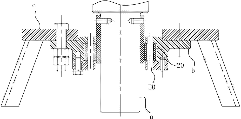
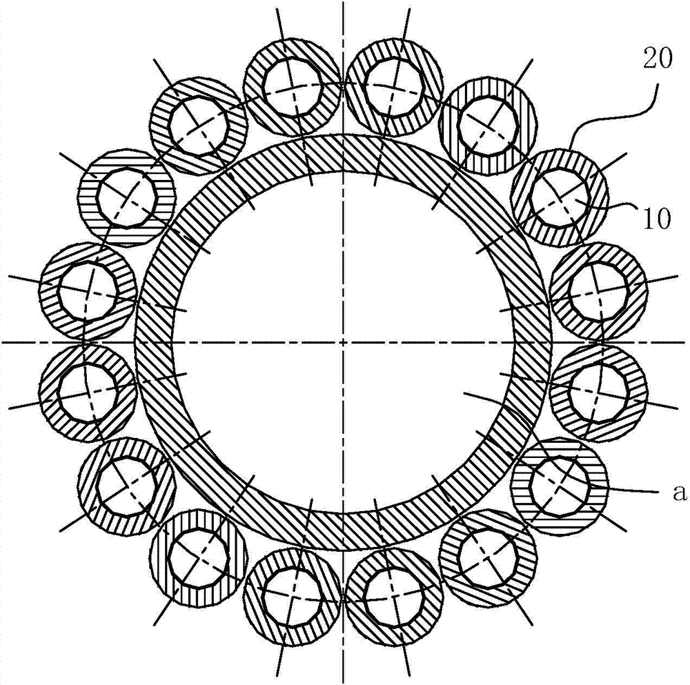
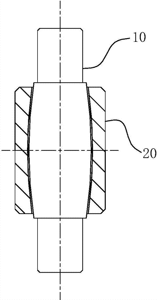
[0027] The practical application structure of the present invention is as Figure 1-2 As shown, it includes a bearing outer ring b sleeved on the shaft body of the stirring shaft 10, and the bearing outer ring b is fixed in the inner cavity of the agitator with a support frame c. The axis of the bearing outer ring b is coaxially arranged with the ideal axis of the stirring shaft a, that is, the axis of the stirring shaft a is in an ideal vertical state, and there is a distance between the hole wall of the bearing outer ring b and the shaft body of the stirring shaft a, So that the agitator shaft a can make a deflection movement within the allowable range. The inner wall of the bearing outer ring b is provided with accommodating grooves along its axis ring, and various components of the present invention are arranged in th...


PUM


Abstract

The invention belongs to the field of structural design of stirring equipment and particularly relates to a self-aligning roll shaft unit. The unit comprises stator shafts and rotating sleeves capable of rotating relatively, wherein the stator shafts are sleeved with the rotating sleeves; matched sections, matched with the rotating sleeves, of the stator shafts are in cambiform structures which are thin at the two ends and thick in the middles; the rotating sleeves are in sleeve structures with concave spherical inner cavities; on axial sections through axes of the stator shafts, the diameters of generatrices of the stator shafts at the matched sections are the same; circle centers of the generatrices are located on the same horizontal plane; circle centers of generatrices of the rotating sleeves at the hole cavities are arranged on the same plane as the circle centers of the generatrices of the stator shafts; diameters of the generatrices of the rotating sleeves at the hole cavities are greater than those of the generatrices of the stator shafts; and when the circle centers of the generatrices of the stator shafts and the rotating sleeves are on the same plane, minimum clearances exist between matching surfaces of shaft bodies of the stator shafts and the hole cavities of the rotating sleeves in radial directions. The unit can be provided with the conventional bearing frame to achieve a shaft body fixing effect of a stirring shaft with an allowable deflection scope, is long in service life and operates stably and reliably.

Description

technical field [0001] The invention belongs to the field of structural design of stirring equipment, and in particular relates to a self-aligning roller shaft unit. Background technique [0002] In the mixing equipment currently produced and sold on the market, the bottom of the stirring shaft basically has a bottomless bearing device, and only relies on the single-axis end fixing at the top of the stirring shaft to achieve the effect of suspension stirring. When the above-mentioned stirring shaft is rotating, the installation of the shaft body is deflected due to the installation error of the stirring shaft, or due to the unbalanced hydrodynamic force acting on the shaft in the horizontal direction during work, or the radial load generated by the weight of the impeller on the stirring shaft Unequally, the lowermost end of the stirring shaft will produce a quantitative swing. In actual work, the above-mentioned deflection of the stirring shaft is allowed to be within a cer...

Claims


Application Information

Patent Timeline
Patent Type & Authority Applications(China)
IPC IPC(8): F16C35/12F16C23/06
Inventor 柴立平李强蔡明虎巫建波何玉杰张军辉
Owner 合肥华升泵阀股份有限公司
Why Eureka
Try Eureka