Leak current fault detecting method and device
A detection method and voltage detection technology, applied in the electric power field, can solve problems such as low leakage fault detection efficiency, and achieve the effect of solving the low detection efficiency and improving the detection efficiency.
- Summary
- Abstract
- Description
- Claims
- Application Information
AI Technical Summary
Problems solved by technology
Method used
Image
Examples
Embodiment 1
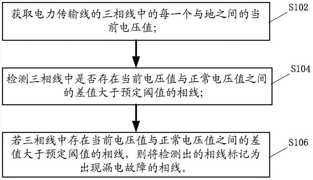
[0026] figure 1 It is a flow chart of an optional leakage fault detection method in the embodiment of the present invention. Such as figure 1 As shown, a detection method for leakage faults, including:
[0027] S102: Obtain the current voltage value between each of the three-phase lines of the power transmission line and the ground;
[0028] S104: Detect whether there is a phase line whose difference between the current voltage value and the normal voltage value is greater than a predetermined threshold in the three-phase line, wherein the normal voltage value is the phase line between the phase line and the ground when no leakage fault occurs on the phase line Voltage value;
[0029] S106: If there is a phase line whose difference between the current voltage value and the normal voltage value is greater than a predetermined threshold among the three-phase lines, mark the detected phase line as a phase line with a leakage fault.
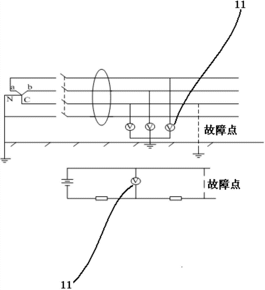
[0030] figure 2 It is a circuit structur...
Embodiment 2
[0038] image 3 It is a flow chart of another leakage fault detection method optional in this embodiment of the present invention.
[0039] Such as image 3 As shown, optionally, obtaining the current voltage value from the voltage detection component arranged between each of the three-phase lines and the ground includes:
[0040] S202: Send a voltage acquisition request to the voltage detection component;
[0041] S204: Receive the current voltage value returned by the voltage detection component.
[0042] For example, send a voltage acquisition request to the voltage detection component voltmeter 11 of the a-phase line, b-phase line and c-phase line, and the voltmeter 11 will return the current voltage obtained in real time. The voltages of the a-phase line and the c-phase line are 218 (V) and 212 (V) respectively, so that the difference between the voltage of the a-phase line and the normal voltage value is 2 (V), within the predetermined threshold range, The difference...
Embodiment 3
[0045] Figure 4 It is a structural block diagram of an optional leakage fault detection device in this embodiment of the present invention.
[0046] Such as Figure 4As shown, optionally, it includes: an acquisition module 1, which is connected to the three-phase lines of the power transmission line respectively, and is used to acquire the current voltage value between each of the three-phase lines of the power transmission line and the ground; the detection module 2, and The acquisition module 1 is connected, and is used to detect whether there is a phase line whose difference between the current voltage value and the normal voltage value is greater than a predetermined threshold value in the three-phase line according to the acquired current voltage value, wherein the normal voltage value is the phase line without leakage The voltage value between the phase line and the ground at the time of fault; the marking module 3 is connected to the detection module 2, and is used to...
PUM
 Abstract
Description
Claims
Application Information
 - R&D
- Intellectual Property
- Life Sciences
- Materials
- Tech Scout
- Unparalleled Data Quality
- Higher Quality Content
- 60% Fewer Hallucinations
Browse by: Latest US Patents, China's latest patents, Technical Efficacy Thesaurus, Application Domain, Technology Topic, Popular Technical Reports.
© 2025 PatSnap. All rights reserved.Legal|Privacy policy|Modern Slavery Act Transparency Statement|Sitemap|About US| Contact US: help@patsnap.com


