Lead storage battery

A lead-acid battery and lead-sleeve technology, applied in lead-acid batteries, battery pack parts, battery caps/end caps, etc., can solve the problems of sacrificing battery capacity performance and service life, unable to ensure liquid leakage, and easy to be damaged, etc. To achieve the effect of excellent vibration resistance and capacity characteristics, good leakage resistance, and avoiding acid climbing

Inactive Publication Date: 2015-04-15
松下蓄电池(沈阳)有限公司 +1
View PDF7 Cites 3 Cited by
  • Summary
  • Abstract
  • Description
  • Claims
  • Application Information

AI Technical Summary

Problems solved by technology

[0006] However, in these lead storage batteries of the prior art, the structure that seals the connecting parts of the middle cover, the pole post and the electrode terminal is easily damaged when the battery is vibrated or the battery is placed on its side, so it cannot be guaranteed that no liquid leakage will occur.
Moreover, these structures will also sacrifice the characteristics of the capacity performance and service life of the battery.

Method used


Image

  • Lead storage battery
  • Lead storage battery
  • Lead storage battery

Examples


Embodiment approach 1

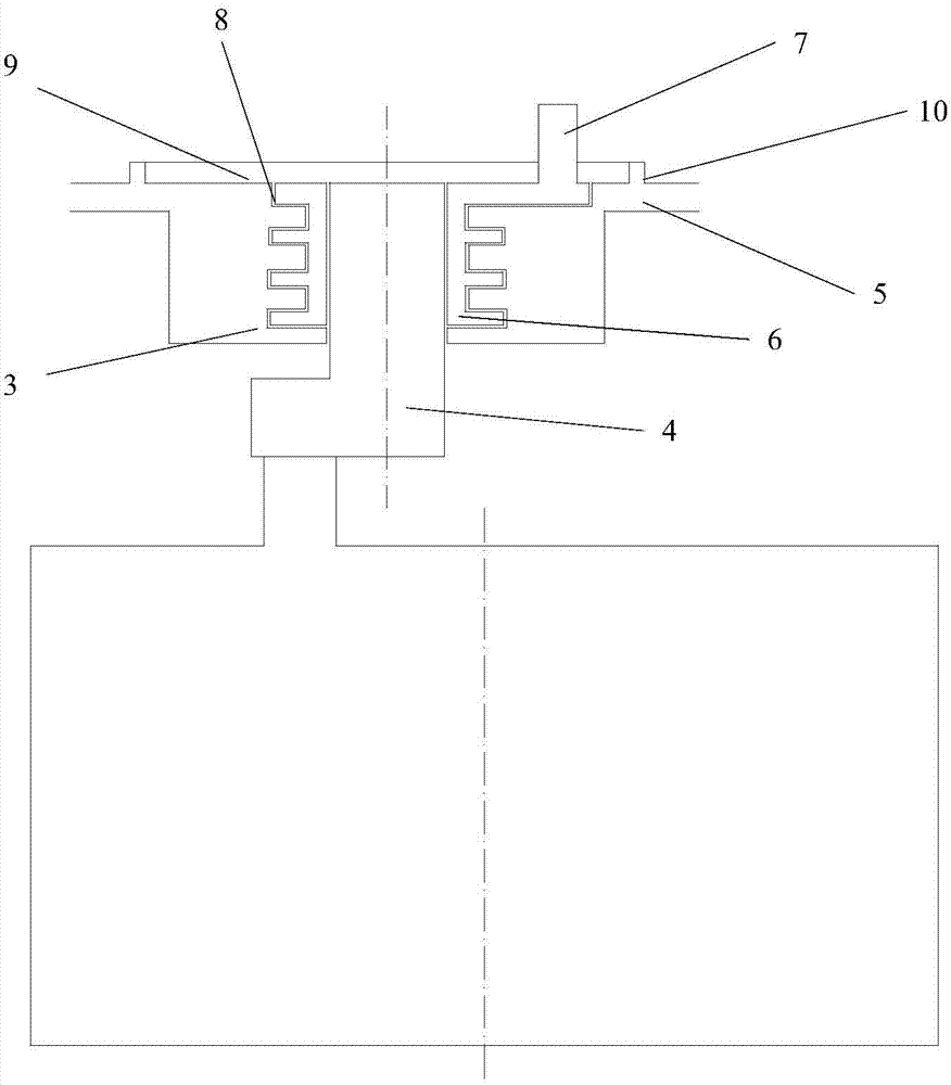
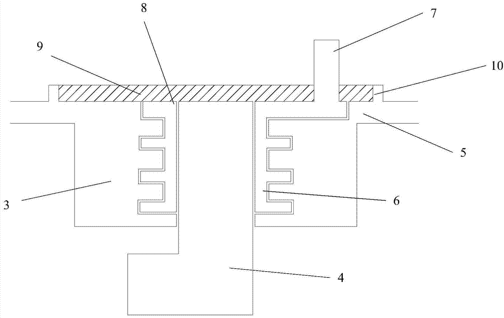
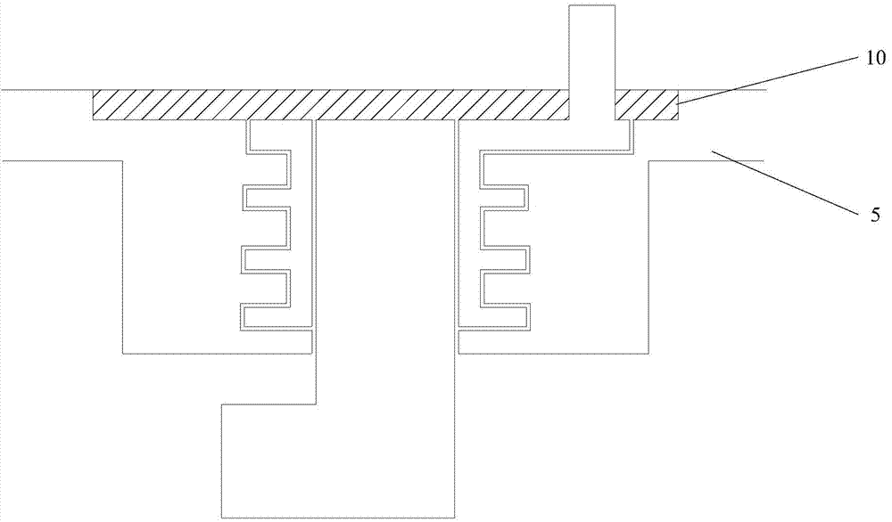
[0063] The lead storage battery of this embodiment is as figure 2 with image 3 As shown, the terminal post 4 is inserted into the tubular lead sleeve 6 pre-embedded in the receiving portion 3 on the lower surface of the middle cover 5 in a penetrating manner, and the above-mentioned terminal post 4 and the above-mentioned tubular lead sleeve 6 are welded Integrate, at least a part of the upper surface of the above-mentioned middle cover 5, the upper end surface of the above-mentioned terminal pole 4 and the upper end surface 6 of the above-mentioned lead sleeve are aligned to form a plane, and the above-mentioned terminal pole 5 and the electrode terminal 7 are welded into one body, at least A resin layer 9 is formed on at least a part of each of the upper surface of the above-mentioned middle cover and the upper end surface of the above-mentioned lead sleeve so as to cover the gap 8 existing at the interface between the above-mentioned lead sleeve 6 and the above-mentioned ...

Embodiment approach 2

[0071] The lead acid battery of Embodiment 2 differs from the lead acid battery of Embodiment 1 only in that the above-mentioned resin layer is not a hot-melt adhesive layer but a photocurable resin adhesive layer. The photocurable resin binder is not particularly limited, and may be, for example, an acrylic monomer oligomer binder or a cationic curing binder mainly used in combination with an epoxy resin.

[0072] According to the final technical effect to be achieved, other constituent elements can be appropriately selected from the foregoing detailed description.

Embodiment approach 3

[0074] The lead acid battery of Embodiment 3 differs from the lead acid battery of Embodiment 1 only in that the above-mentioned resin layer is not a photocurable resin adhesive layer, but is made of a material other than a photocurable resin adhesive or a hot-melt adhesive. An adhesive resin layer such as an epoxy resin layer is formed.

[0075] According to the final technical effect to be achieved, other constituent elements can be appropriately selected from the foregoing detailed description.


PUM

PropertyMeasurementUnit
Thicknessaaaaaaaaaa
Thicknessaaaaaaaaaa
Thicknessaaaaaaaaaa

Abstract

The invention provides a lead storage battery which is provided with an electrolytic bath, a middle cover (5), an electrode plate group and a terminal post (4). The terminal post (4) is inserted into a tubular lead sleeve (6), which is pre-embedded into the middle cover (5) in a through manner, and is welded to the tubular lead sleeve (6) in an integrated manner. At least a part of the top surface of the middle cover (5), the top surface of the terminal post (4) and the top surface of the lead sleeve (6) are aligned at one plane. The terminal post (4) and an electrode terminal (7) are welded in an integrated manner. A resin layer (9) is formed on at least a part of the plane in a manner of covering a gap (8) existing at an interface between the lead sleeve (6) and the middle cover (5), wherein the thickness of the resin layer (9) in the plane is 1.0-3.0mm. The lead storage battery can effectively avoid acid leakage in the gap (8), so that the lead storage battery is excellent in anti-liquid leakage property and is excellent in vibration resistance and capacity characteristic.

Description

technical field [0001] The present invention relates to a lead-acid battery, and specifically relates to a lead-acid battery having excellent vibration resistance and liquid leakage resistance, and excellent capacity characteristics. Background technique [0002] Lead-acid batteries are not only used for starting vehicle power supply, lighting power supply and backup power supply, but also widely used for main power supply, that is, as a power supply for independent charging and discharging equipment such as electric vehicles, electric forklifts, electric forklifts, electric buses, electric bicycles, Power sources for electric motorcycles, electric scooters, small electric mopeds, golf carts, electric locomotives, etc., and electric energy storage devices such as solar batteries. In these applications, the current of the lead-acid battery is large when starting, and during use, the vehicle is running on the road or in the countryside, with a lot of bumps, and the two electro...

Claims


Application Information

Patent Timeline
IPC IPC(8): H01M2/04H01M2/08H01M2/30H01M10/06H01M50/14H01M50/148H01M50/188H01M50/193H01M50/198H01M50/552H01M50/566
CPCH01M10/06H01M50/147H01M50/148H01M50/183H01M50/543Y02E60/10
Inventor 潘宇亮孙勤超白春宇中岛孝佐佐木健浩
Owner 松下蓄电池(沈阳)有限公司
Why Eureka
Try Eureka