
Battery gasket and alkaline battery using the same

Active Publication Date: 2010-09-30
PANASONIC CORP
View PDF5 Cites 4 Cited by
  • Summary
  • Abstract
  • Description
  • Claims
  • Application Information

AI Technical Summary

Benefits of technology

[0006]In arranging the gate for injecting the molten resin to correspond to the end face of the boss portion of the gasket, it is reasonable to arrange the gate in the injection mold to correspond to an end face of the boss portion facing a gelled negative electrode for easy manufacture and maintenance of the injection mold.
[0008]In order to solve the foregoing problem, the present disclosure advantageously provides a leak-proof battery gasket capable of preventing leakage of the electrolyte during long-term storage of the battery.
[0012]The gasket thus configured can prevent cracking of the boss portion of the gasket near the gate, and can prevent leakage of an electrolyte from an alkaline battery using the gasket during long-term storage of the alkaline battery. This can provide the alkaline battery with good leakage resistance.
[0016]The disclosed gasket can prevent cracking of the boss portion of the gasket near the gate. This structure can prevent leakage of an electrolyte from an alkaline battery using the gasket during long-term storage of the alkaline battery, and can provide the alkaline battery with good leakage resistance.

Problems solved by technology

However, when the gasket is injection molded, the boss portion near the gate may easily crack due to residual stress of the injection molding.
If part of the boss portion facing the gelled negative electrode (facing the inside of the battery) cracks, the gasket is hydrolyzed by an alkaline electrolyte contained in the gelled negative electrode, and tends to degrade over time.
As a result, the electrolyte may leak through the crack in the gasket during long-term storage of the battery.

Method used


Image

  • Battery gasket and alkaline battery using the same
  • Battery gasket and alkaline battery using the same
  • Battery gasket and alkaline battery using the same

Examples


first embodiment

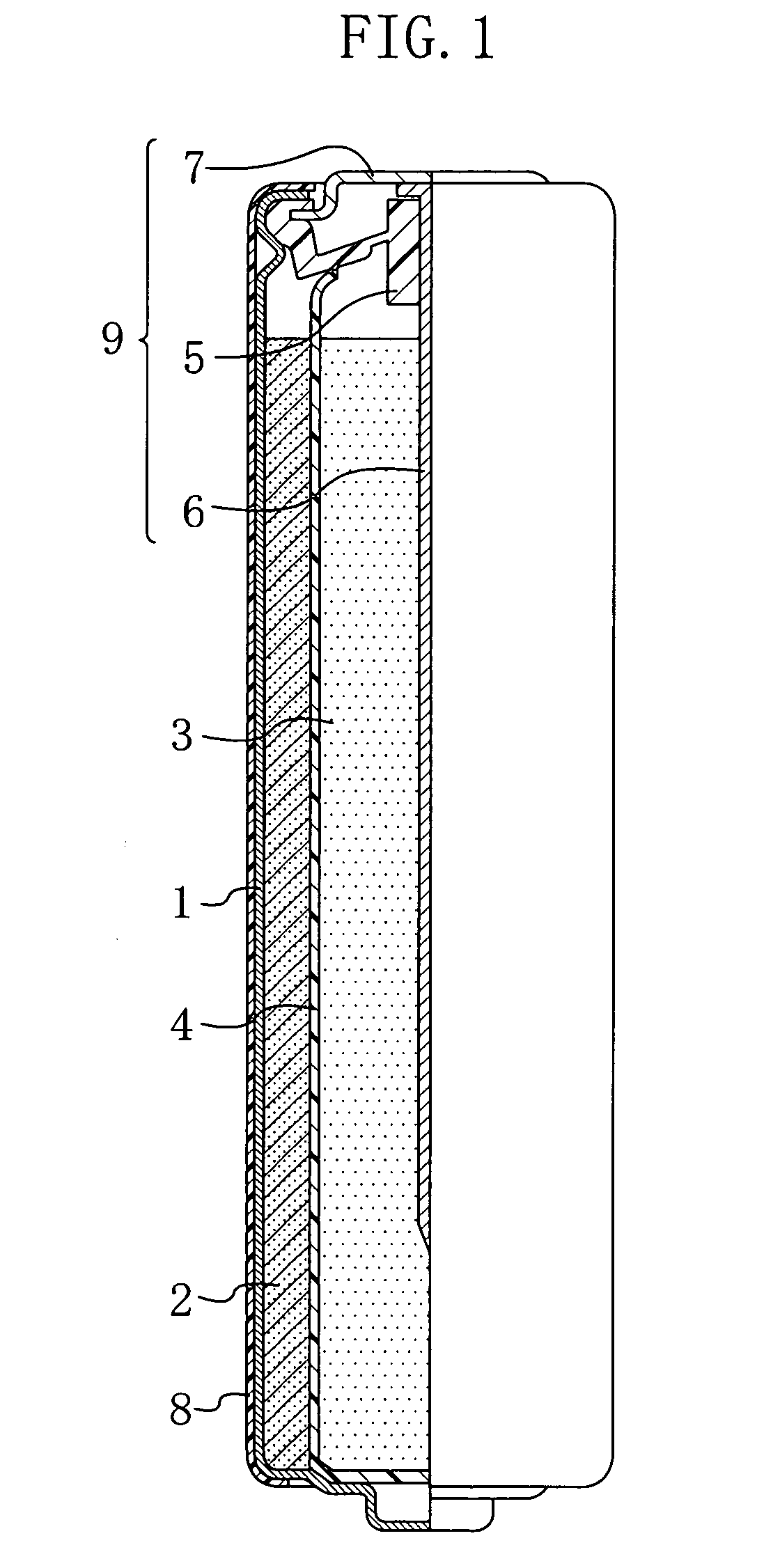
[0026]FIG. 1 is a view, half in cross-section, schematically illustrating the structure of a cylindrical alkaline battery in which a battery case is sealed with a gasket of the first embodiment of the invention.

[0027]As shown in FIG. 1, a closed-end, cylindrical battery case 1 contains a positive electrode 2 and a gelled negative electrode 3 with a separator 4 interposed therebetween, and an opening of the battery case 1 is sealed with a sealing unit 9 integral with a gasket 5, a negative electrode current collector 6, and a negative electrode terminal plate 7.

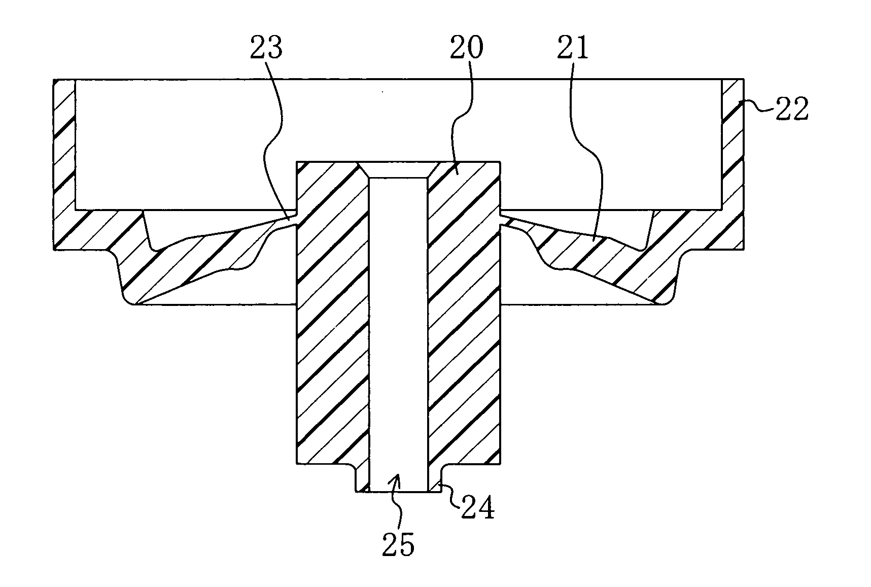
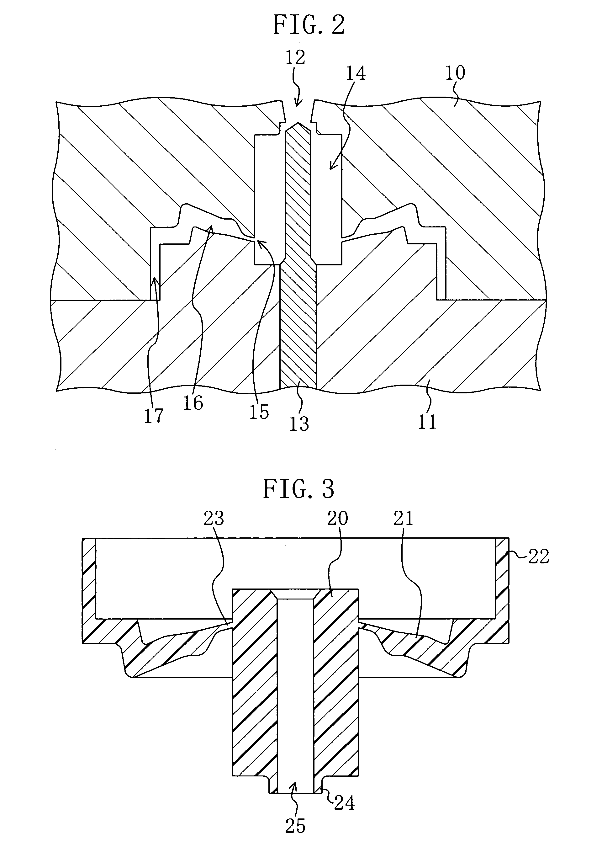
[0028]FIG. 2 is a cross-sectional view illustrating an injection mold for injection molding the gasket 5. The injection mold is a combination of an upper mold 10 and a lower mold 11, and forms a cavity 14 for forming a boss portion, a cavity 16 for forming a connecting portion, and a cavity 17 for forming a rim portion. A core pin 13 for forming a through hole in which the current collector 6 is inserted is arranged in the cav...


PUM


Abstract

A gasket is made of an injection molded resin integral with a cylindrical boss portion having a through hole in which a current collector is inserted, a rim portion for sealing an opening of a battery case, and a connecting portion for connecting the boss portion and the rim portion, wherein the boss portion has an annular injection portion at an end face thereof, which is a trace of an injection molding gate, a ratio (S1 / S2) between an axial cross-sectional area (S1) of the boss portion and an axial cross-sectional area (S2) of the injection portion is in the range of 10 to 25, and an outer diameter of the boss portion is in the range of 3.0 to 4.2 mm.

Description

CROSS-REFERENCE TO RELATED APPLICATION[0001]This application claims priority to Japanese Patent Application No. 2009-079735 filed on Mar. 27, 2009, the disclosure of which including the specification, the drawings, and the claims is hereby incorporated by reference in its entirety.BACKGROUND[0002]The present disclosure relates generally to a battery gasket for sealing an opening of a battery case, and an alkaline battery using the same.[0003]A cylindrical alkaline battery is configured by placing battery components in a battery case, and sealing an opening of the battery case with a gasket.[0004]In general, a gasket includes a cylindrical boss portion having a through hole in which a current collector is inserted, a rim portion for sealing an opening of a battery case, and a connecting portion for connecting the boss portion and the rim portion. The gasket thus configured is integrally injection molded by injecting a molten resin into an injection mold.[0005]In injection molding the...

Claims


Application Information

Patent Timeline
IPC IPC(8): H01M2/08H01M50/107H01M50/166H01M50/184H01M50/193
CPCH01M2/0202H01M2/022Y02E60/124H01M2/08H01M10/24H01M2/0413Y02E60/10H01M50/107H01M50/166H01M50/171H01M50/184H01M50/193
Inventor MATSUHISA, ICHIROKATO, SUSUMU
Owner PANASONIC CORP
Learn More