
Mobile phone

A technology of mobile phones and optical components, applied in the field of electronics, can solve the problems of large diffusion angle, limited use, short lighting distance, etc.

Inactive Publication Date: 2015-04-15
HONG FU JIN PRECISION IND (SHENZHEN) CO LTD +1
View PDF4 Cites 3 Cited by
  • Summary
  • Abstract
  • Description
  • Claims
  • Application Information

AI Technical Summary

Problems solved by technology

However, when using the flash of a mobile phone as a flashlight, its use is limited due to its large diffusion angle and short lighting distance.

Method used


Image

  • Mobile phone
  • Mobile phone
  • Mobile phone

Examples


Embodiment Construction

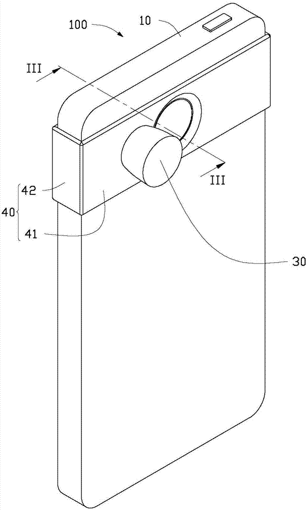
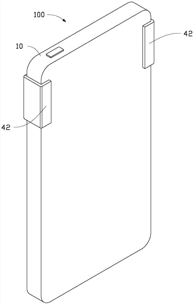
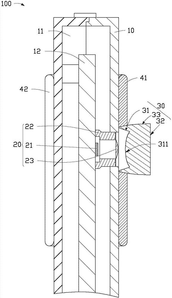
[0012] see figure 1 , figure 2 and image 3 , the mobile phone 100 provided by the embodiment of the present invention includes a mobile phone main body 10 , a light source 20 , an optical element 30 and a fixing unit 40 .

[0013] In this embodiment, the mobile phone body 10 forms a receiving space 11 . The mobile phone motherboard 12 is accommodated in the accommodation space 11 .

[0014] The light source 20 is accommodated in the accommodation space 11 , and includes a light emitting element 21 , a supporting portion 22 surrounding the light emitting element 21 , and a lens 23 located on the light emitting surface of the light emitting element 21 . In this embodiment, the light emitting element 21 is a light emitting diode, which is arranged on the main board 12 of the mobile phone. The lens 23 is disposed on the supporting portion 22 and is a convex lens. A plurality of ring-shaped convex ribs are formed on the surface of the supporting portion 22, which together wi...


PUM


Abstract

The invention relates to a mobile phone comprising a mobile phone body, a light source and an optical element. An accommodating space is formed in the mobile phone body, and the light source is accommodated in the accommodating space. The optical element is detachably arranged outside the mobile phone body and located on a light path of the light source, and light emitted by the light source is converged and emitted out after passing through the optical element.

Description

technical field [0001] The invention relates to the field of electronics, in particular to a mobile phone. Background technique [0002] A traditional mobile phone with a camera function is generally equipped with a flash to meet the demand for supplementary light in the photographing environment. Due to the limited space of the mobile phone, the flash generally uses a Fresnel lens to achieve a uniform light diffusion effect within a short distance. However, when the flashlight of a mobile phone is used as a flashlight, its use is limited due to its large diffusion angle and short lighting distance. Contents of the invention [0003] In view of this, it is necessary to provide a mobile phone with a variable light emitting angle. [0004] A mobile phone, which includes a mobile phone main body, a light source and an optical element. The main body of the mobile phone forms a receiving space. The light source is accommodated in the accommodation space. The optical elemen...

Claims


Application Information

Patent Timeline
IPC IPC(8): H04M1/21
Inventor 郭章纬
Owner HONG FU JIN PRECISION IND (SHENZHEN) CO LTD
Learn More