
A light guide plate driving circuit based on pwm dimming

A driving circuit and light guide plate technology, applied in the field of light guide plates, can solve the problems of low static drive power, small package transistors that cannot meet the design of high current, small package and large passing current, etc.

Inactive Publication Date: 2019-01-08
SHANGHAI AVIATION ELECTRIC
View PDF4 Cites 0 Cited by
  • Summary
  • Abstract
  • Description
  • Claims
  • Application Information

AI Technical Summary

Problems solved by technology

However, ordinary small-package triodes can no longer meet the design of large currents. The triode is a current-driven electrical component, and the MOS tube is a voltage-driven electrical component. Its input impedance is high, the required static driving power is small, and the package is small and the current is large. However, due to the parasitic capacitance between the poles, the drive circuit must be able to quickly charge / discharge its parasitic capacitance during turn-on and turn-off, especially in high-frequency applications

Method used


Image

  • A light guide plate driving circuit based on pwm dimming

Examples


Embodiment Construction

[0013] The present invention will be described in detail below in conjunction with the accompanying drawings and embodiments.

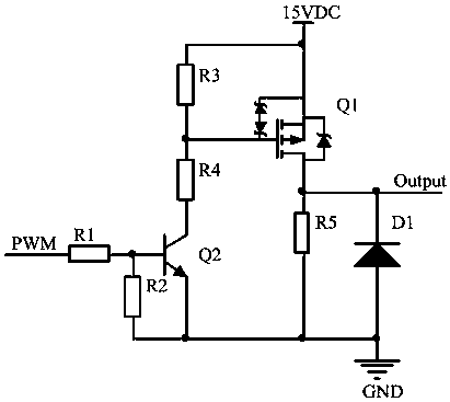
[0014] See figure 1 , shown in the figure is a light guide plate drive circuit based on PWM dimming, which is mainly composed of a PWM signal input terminal, a PWM signal output terminal, a light guide plate dimming power supply circuit and a waveform adjustment circuit.

[0015] The PWM signal input end is used to provide an input signal. The PWM signal output end is used to provide an output signal.

[0016] The light guide plate dimming power supply circuit:

[0017] The PWM signal input end is respectively connected to the first end of a second resistor R2 and the base of a second triode Q2 through a first resistor R1, and the collector of the second transistor Q2 is connected to a first end of a second transistor Q2 through a first resistor R1. The four resistors R4 are respectively connected to the first end of a third resistor R3 and the gat...


PUM


Abstract

The invention relates to a PWM (pulse-width modulation) dimming based light guide plate driving circuit. The PWM dimming based light guide plate driving circuit mainly comprises a PWM signal input end, a PWM signal output end, a light guide plate dimming power circuit and a waveform adjusting circuit. The light guide plate dimming power circuit is used for changing a duty ratio of an input signal received from the PWM signal input end to form an output signal which is outputted through the PWM signal output end. The PWM dimming based light guide plate driving circuit has the advantages that a novel light guide plate dimming driving mode is provided, dimming is realized by adjusting the PWM duty ratio, and the problem of slight brightness of LEDs (light emitting diodes) in a light guide plate when the LEDs are off is well solved while the protection problem of influences of inductive load and capacitive load on circuits is solved as well.

Description

technical field [0001] The invention relates to a light guide plate in an airborne device, in particular to a light guide plate driving circuit based on PWM dimming. Background technique [0002] Light guide plate is an indispensable lighting element in airborne equipment, mainly used for character lighting and information display. With the development of the aviation industry today, higher and higher requirements are put forward for airborne equipment. The design of the light guide plate drive needs to consider the redundancy design of the extreme environment. The applicant found that in a high temperature environment, when the light guide plate works under standard conditions The rated current cannot satisfy its operation in high temperature environment, so when designing the drive circuit, it is necessary to amplify the rated current by 3-4 times to design. However, ordinary small-package triodes can no longer meet the design of large currents. The triode is a current-dr...

Claims


Application Information

Patent Timeline
Patent Type & Authority Patents(China)
IPC IPC(8): H05B37/02
Inventor 崔利家
Owner SHANGHAI AVIATION ELECTRIC
Learn More