
Circuit for reducing standby power consumption and electronic equipment

A technology of standby power consumption and circuit, applied in the field of LED drive power supply, can solve the problem of light bead micro-brightness and so on

Inactive Publication Date: 2019-12-27
MINGFENG POWER ELECTRONICS IND CO LTD
View PDF7 Cites 1 Cited by
  • Summary
  • Abstract
  • Description
  • Claims
  • Application Information

AI Technical Summary

Problems solved by technology

[0003] Aiming at the problems of the background technology, the present invention provides a circuit and electronic equipment for reducing standby power consumption, so as to reduce the standby power and solve the problem that the lamp beads are slightly bright during non-isolated shutdown;

Method used


Image

  • Circuit for reducing standby power consumption and electronic equipment
  • Circuit for reducing standby power consumption and electronic equipment
  • Circuit for reducing standby power consumption and electronic equipment

Examples


Embodiment Construction

[0018] The following will clearly and completely describe the technical solutions in the embodiments of the present invention with reference to the accompanying drawings in the embodiments of the present invention. Obviously, the described embodiments are only part of the embodiments of the present invention, not all of them. Based on the embodiments of the present invention, all other embodiments obtained by persons of ordinary skill in the art without creative efforts fall within the protection scope of the present invention.

[0019] It should be noted that if there is a directional indication (such as up, down, left, right, front, back...) in the embodiment of the present invention, the directional indication is only used to explain the position in a certain posture (as shown in the accompanying drawing). If the specific posture changes, the directional indication will also change accordingly.

[0020] In addition, if there are descriptions involving "first", "second" and ...


PUM


Abstract

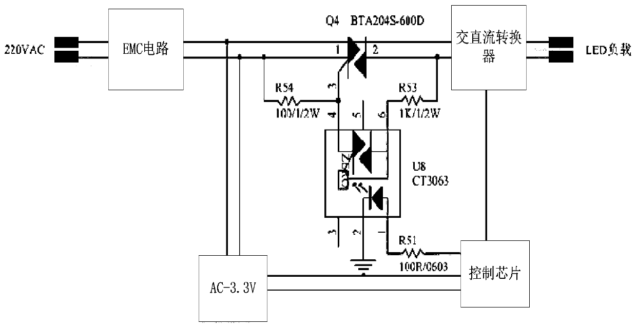
The invention discloses a circuit for reducing standby power consumption and electronic equipment and belongs to the technical field of LED driving power sources. The circuit comprises an EMC circuit,an alternating current-direct current converter, a control chip and an AC-3.3V converter; the circuit also comprises a silicon controlled rectifier and an optical coupler; one end of the EMC circuitis connected with 220V alternating current; the other end of the EMC circuit is connected with one end of the alternating current-direct current converter through the silicon controlled rectifier; theother end of the alternating current-direct current converter is connected with an LED load; the control end of the control chip is connected with the first end of the optical coupler; the second endof the optical coupler is connected with the control end of the silicon controlled rectifier; one end of the AC-3.3V converter is connected with the other end of the EMC circuit; and the other end ofthe AC-3.3V converter is connected with the power source end of the control chip; The circuit structure can reduce power consumption and realize an energy-saving effect under a standby state. With the circuit adopted, the problem that a lamp bead is slightly bright during non-isolated shutdown is solved, and a condition that a terminal user can be prevented from mistakenly considering that a lampis not turned off.

Description

technical field [0001] The invention relates to the technical field of LED drive power supply, in particular to a circuit and electronic equipment for reducing standby power consumption. Background technique [0002] At present, existing commonly used circuits such as figure 1 As shown, its working principle is: input AC 220V into 3.3V, supply power to the intelligent module, and control the current of the AC-DC module through the PWM signal, so as to realize the dimming function; the defects of the circuit structure are: 2.4G, wifi , Bluetooth and other LED intelligent remote control dimming products have a high power during standby, reaching more than 1W; the existing non-isolated products have a problem that the lamp beads are slightly bright when the light is turned off. Contents of the invention [0003] Aiming at the problems of the background technology, the present invention provides a circuit and electronic equipment for reducing standby power consumption, so as ...

Claims


Application Information

Patent Timeline
Patent Type & Authority Applications(China)
IPC IPC(8): H05B33/08H05B44/00
Inventor 胡源洲
Owner MINGFENG POWER ELECTRONICS IND CO LTD
Learn More