The electromagnetic valve

A solenoid valve and valve hole technology, applied in the field of solenoid valves, can solve the problem of inability to generate electromagnetic force, and achieve the effect of cheap implementation and easy production

Inactive Publication Date: 2016-09-28
TOYOTA JIDOSHA KK
View PDF8 Cites 0 Cited by
  • Summary
  • Abstract
  • Description
  • Claims
  • Application Information

AI Technical Summary

Problems solved by technology

However, in the solenoid valve described in the above-mentioned Patent Document 1, the attracting portion (one end portion) of the movable core (the plunger core) is surrounded from the outer periphery by the non-magnetic portion provided on the cylindrical portion of the case, so that the non-magnetic One side of the axial direction (fixed core side), and the direction perpendicular to the axis (diameter direction), the electromagnetic force perpendicular to the axis (radial direction) generates frictional resistance relative to the axial movement of the movable core (plunger core)

Method used


Image

  • The electromagnetic valve
  • The electromagnetic valve

Examples


Embodiment Construction

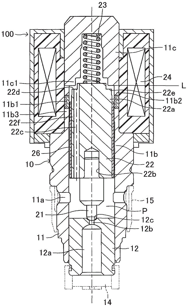
[0019] Embodiments of the present invention will be described below based on the drawings. figure 1 An embodiment of a solenoid valve according to the present invention is shown in . The solenoid valve 100 is, for example, a hydraulic control device incorporated in a hydraulic brake system for a vehicle, and is a normally closed solenoid valve used for hydraulic control of brake fluid. In addition, in this solenoid valve 100 , a valve element 21 , a movable iron core 22 , a spring 23 , a coil 24 , and the like are assembled in the case 10 .

[0020] The housing 10 includes a cylindrical housing main body 11 and a cylindrical seat member 12 assembled to the inner periphery of the lower end portion of the housing main body 11 so as to be positionally adjustable in the vertical direction. The housing main body 11 houses a valve element 21, a movable iron core 22, a spring 23, and the like inside, and is provided with a plurality of fluid outlets 11a on the lower side in the drawi...


PUM


Abstract

The present invention provides a solenoid valve. A solenoid valve (100) includes a case (10), a valve core (21), a movable iron core (22), a spring (23), a coil (24), and a fixed iron core (11c). The casing (10) has a cylindrical portion (11b) for accommodating a movable iron core (22) in an axially movable manner. The axial middle part of the cylindrical part (11b) is composed of a non-magnetic part (11b1) surrounding the outer periphery of the axial middle part of the movable iron core (22), and both axial sides of the nonmagnetic part (11b1) are formed by surrounding the movable iron core ( 22) One side magnetic part (11b2) and the other side magnetic part (11b3) on the outer periphery are constituted. It is set: on one axial side of the nonmagnetic part (11b1), between the outer circumference of the movable iron core (22) and the magnetic part (11b2) on one side of the cylindrical part (11b), and between the nonmagnetic part (11b1 ) between the outer periphery of the movable iron (22) on the other side in the axial direction and the magnetic part (11b3) on the other side of the cylindrical part (11b), the direction perpendicular to the axis is generated by energizing the coil (24). An electromagnetic force that generates frictional resistance relative to the axial movement of the movable core (22).

Description

technical field [0001] The present invention relates to a solenoid valve, for example, a solenoid valve for hydraulic control of brake fluid (fluid) incorporated in a hydraulic control device of a hydraulic brake device for a vehicle. Background technique [0002] As one of such solenoid valves, for example, the following patent document 1 discloses a solenoid valve that includes a housing provided with an inlet and an outlet of a fluid and a passage communicating with the inlet and outlet. , a valve hole having a valve seat at one end is provided in the passage, the housing has a cylindrical portion coaxial with the valve hole; Seat; movable iron core (also called plunger type iron core), which is assembled to the above-mentioned cylindrical part in a manner that can move integrally with the valve core in the axial direction; spring, which acts on the above-mentioned valve core and the above-mentioned movable core. The iron core exerts a force in the direction of seating o...

Claims


Application Information

Patent Timeline
Patent Type & Authority Patents(China)
IPC IPC(8): F16K31/06
CPCF16K27/029F16K31/0665F16K31/0675B60T8/363H01F2007/085F16K11/04F16K31/0624
Inventor 铃木雅邦七原正辉佐藤圭金盛且洋石田岳史
Owner TOYOTA JIDOSHA KK
Why Eureka
Try Eureka