A metal 3d printer

A 3D printer, metal technology

Active Publication Date: 2017-01-04
JIANGSU YOUCHENG CNC TECH CO LTD
View PDF4 Cites 1 Cited by
  • Summary
  • Abstract
  • Description
  • Claims
  • Application Information

AI Technical Summary

Problems solved by technology

[0003] In order to solve the problem of sagging and deformation in the prior art when the metal is melted and piled up if there is no support below, the present invention provides a simple structure, easy to use, and can meet the needs of printing production of different materials and complex part structures. Metal 3D printer

Method used


Image

  • A metal 3d printer

Examples


Embodiment Construction

[0025] The present invention will be further described below in conjunction with accompanying drawing.

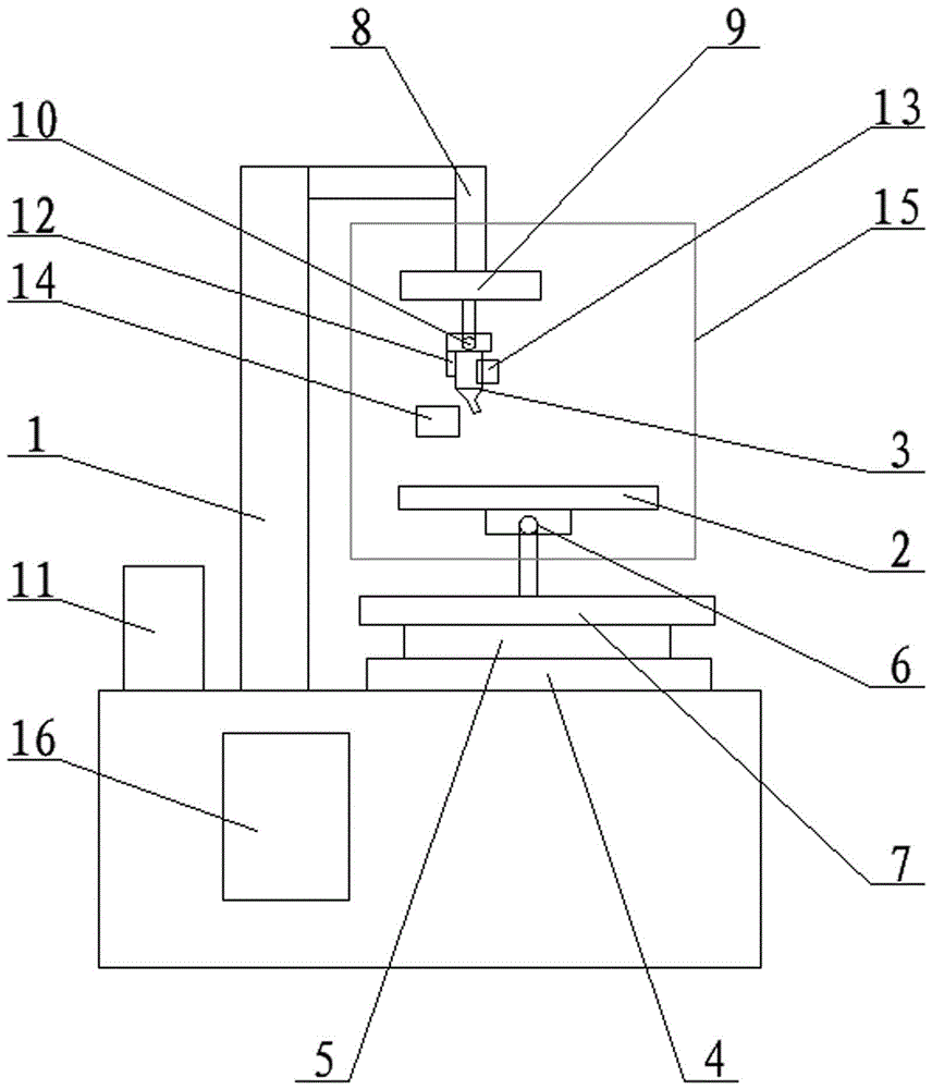
[0026] figure 1 As shown, a metal 3D printer includes a frame 1, a workbench 2, a print head 3, a workbench transverse movement mechanism 4, a workbench longitudinal movement mechanism 5, a workbench vertical rotation mechanism 6, a workbench horizontal rotation mechanism 7, a printing Head vertical linear motion mechanism 8, print head horizontal rotation mechanism 9, print head vertical rotation mechanism 10, metal wire storage mechanism 11, deceleration feeding mechanism 12, metal heating mechanism 13, cooling mechanism 14, gas protection mechanism 15 and electric control Box 16. The frame 1 is supported with a workbench transverse movement mechanism 4 and a workbench longitudinal movement mechanism 5 which are superimposed on each other. The workbench horizontal rotation mechanism 7 is installed on the workbench transverse movement mechanism 4 or the workbench longitud...


PUM


Abstract

The invention relates to a metal 3D printer which comprises a rack, a working table, a working table moving mechanism, a printing head moving mechanism, a printing head, a feeding mechanism and an electric control box. The metal 3D printer is characterized in that the working table moving mechanism comprises a working table transverse moving mechanism driving the working table to move transversely, a working table longitudinal mechanism driving the working table to move longitudinally, a working table vertical rotating mechanism driving the working table to rotate vertically, and a working table horizontal rotating mechanism driving the working table to rotate horizontally. The printing head moving mechanism comprises a printing head vertical linear moving mechanism driving the printing head to move vertically, a printing head horizontal rotating mechanism driving the printing head to rotate horizontally, and a printing head vertical rotating mechanism driving the printing head to rotate vertically.

Description

technical field [0001] The invention relates to a 3D printer, in particular to a metal 3D printer. Background technique [0002] Traditional metal 3D printers are only equipped with X, Y, and Z axes, and can only print some simple parts. However, in actual production and use, because the metal will sag and deform when it is piled up after melting, so for some Complicated hollow parts cannot produce products that meet the requirements, which affects the practical promotion of 3D printing technology. Contents of the invention [0003] In order to solve the problem of sagging and deformation in the prior art when the metal is melted and piled up when there is no support below, the present invention provides a simple structure, easy to use, and can meet the needs of printing production of different materials and complex part structures. Metal 3D printers. [0004] The technical solution adopted in the present invention is: a metal 3D printer, comprising a frame, a workbench,...

Claims


Application Information

Patent Timeline
Patent Type & Authority Patents(China)
IPC IPC(8): B22F3/115
Inventor 王勇
Owner JIANGSU YOUCHENG CNC TECH CO LTD
Why Eureka
Try Eureka