
Motor drive multi-shaft combined mechanical arm system

A motor-driven, robotic arm technology, applied in manipulators, program-controlled manipulators, manufacturing tools, etc., can solve problems such as movement restrictions, high production costs, and unreasonable movement modes of robotic arm devices, achieving a wide range of applications and reducing replacement. the effect of demand

Pending Publication Date: 2018-06-15
东莞市特力精密夹具有限公司
View PDF0 Cites 0 Cited by
  • Summary
  • Abstract
  • Description
  • Claims
  • Application Information

AI Technical Summary

Problems solved by technology

[0004] However, the movement methods of many traditional mechanical arm devices are unreasonable, and their movement in space is often restricted, or in other words, they cannot move to any angle or direction in a certain space to meet the needs of actual industrial production. This limitation greatly affects its application range and places
[0005] Those skilled in the art have analyzed the defects of the existing known technologies and found that most of the existing mechanical arms are single-axis or multi-axis mechanical arms. Axis or multi-axis manipulators, if the number of axes of the manipulator is arbitrarily increased or decreased according to different usage requirements, many manipulators will be equipped with corresponding auxiliary equipment or combined with different manipulators, resulting in complex production methods , the production cost is relatively high, for example, there is no simple and effective way to make the mechanical arm realize the rotation adjustment between the horizontal plane and the vertical plane

Method used


Image

  • Motor drive multi-shaft combined mechanical arm system
  • Motor drive multi-shaft combined mechanical arm system
  • Motor drive multi-shaft combined mechanical arm system

Examples


Embodiment 1

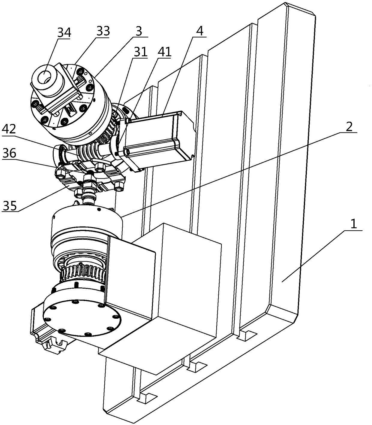
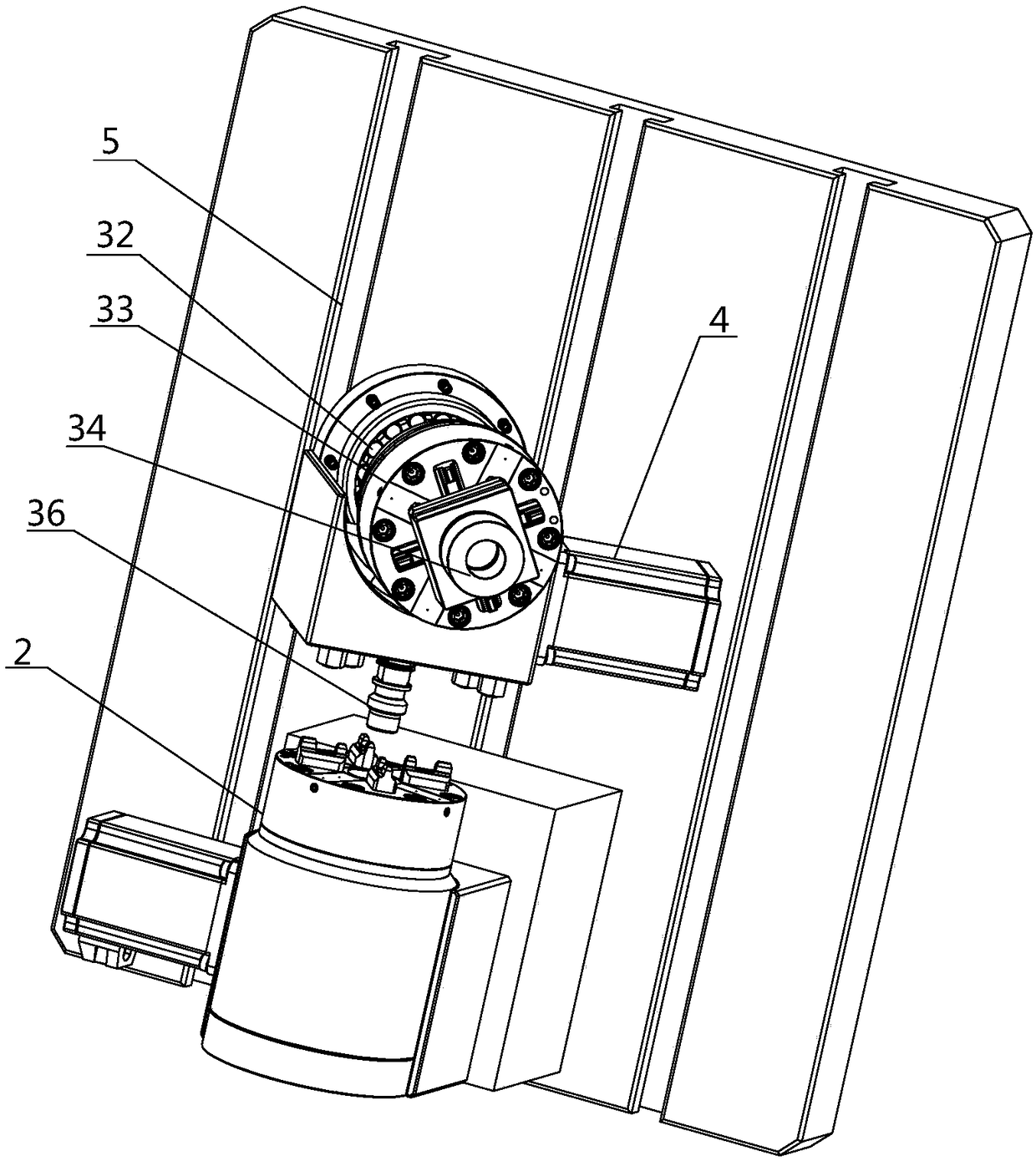
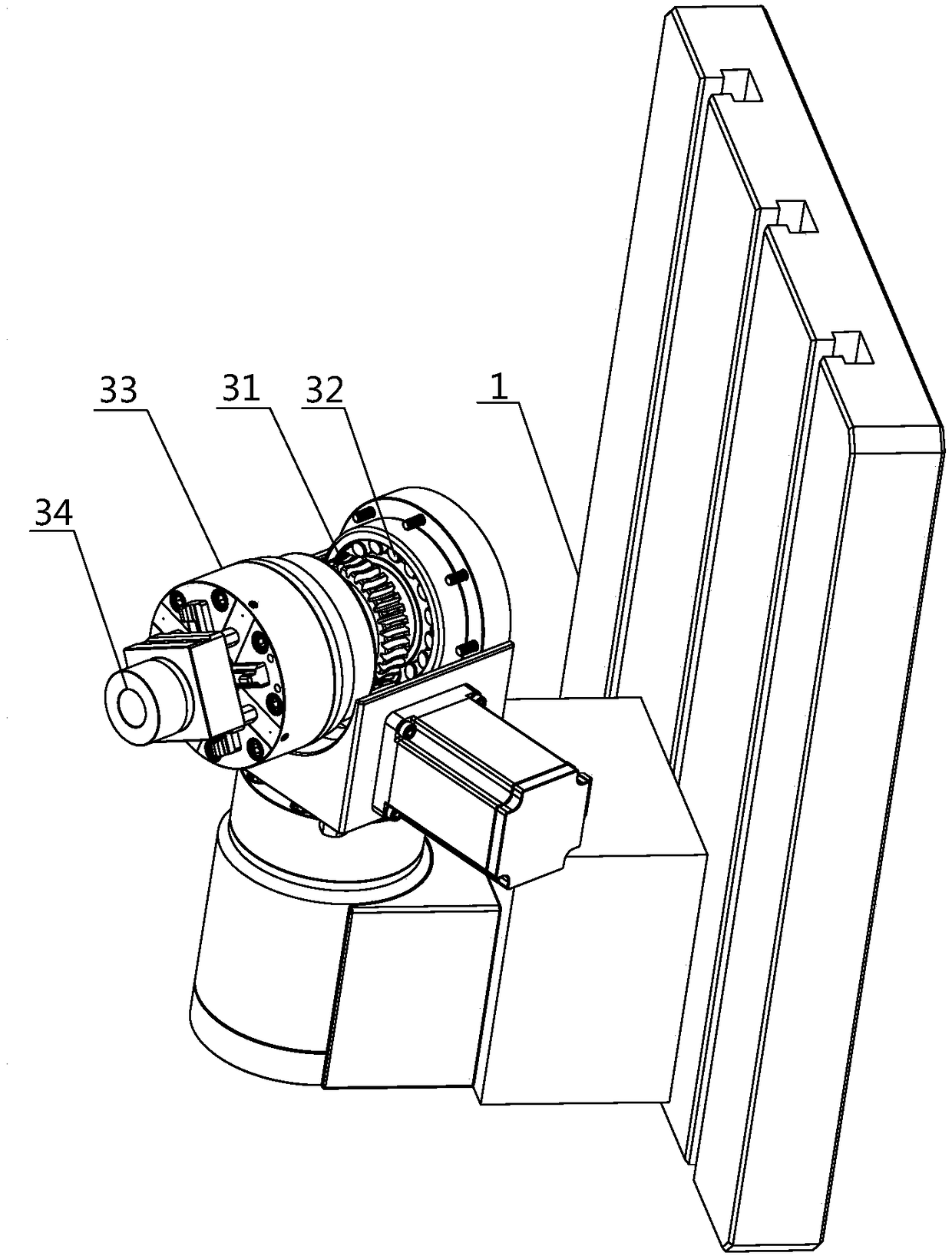
[0036] Such as Figure 1-3 As shown, the motor-driven multi-axis combined manipulator system described in Embodiment 1 of the present invention, the purpose of the implemented technical means is to solve the problem of traditional manipulator equipment when single-axis or multi-axis work is required. In addition, the replacement of the matching single-axis or multi-axis manipulator leads to the technical problem that the multi-axis work cannot be achieved through the single-axis manipulator. Rotation and position adjustment, therefore, the technical solution implemented by the present invention firstly includes a vertical fixed frame 1 arranged vertically.

[0037] Analyze the structure of the vertical fixed rack 1 set above:

[0038] The implemented fixed frame 1 adopts equipment with a single-axis mechanical arm or is fixedly equipped with a vertical direction single-axis mechanical arm 2 on the basis of traditional mechanical arm equipment. At the same time, in order to co...

Embodiment 2

[0044] Such as Figure 1-3 As shown, the motor-driven multi-axis combined manipulator system described in Embodiment 2 of the present invention is a modification made on the basis of Embodiment 1. It belongs to the same concept as the technical solution implemented in Embodiment 1 and solves the same problem. Technical problem, the technical means implemented is to connect different shapes of mechanical arm components at the connection port of the horizontal single-axis mechanical arm 3, and realize the rotation within 360° with the rotation of the gear 31. At the same time, due to the vertical direction The single-axis mechanical arm 2 and the horizontal single-axis mechanical arm 3 are flexibly connected, so that the horizontal single-axis mechanical arm 3 can adjust its position through rotation in the vertical space.

[0045] Further, there are several rails 5 on the implemented fixed frame 1 that allow the vertical single-axis manipulator 3 to slide in the vertical direct...

Embodiment 3

[0049] Such as Figure 1-3 As shown, the motor-driven multi-axis combined manipulator system described in Embodiment 3 of the present invention is a modification based on Embodiment 1 and Embodiment 2, and is the same as the technical solution implemented in Embodiment 1 and Embodiment 2. It belongs to the same idea and solves the same technical problem. The implemented technical means is that the outer end surface of each single-axis manipulator has a connecting shaft hole for connecting another added single-axis manipulator, and the rotating shaft installed through the connecting shaft hole The assembly turns another added single-axis robotic arm.

[0050] Correspondingly, the horizontal single-axis mechanical arm is connected to different numbers of vertical or horizontal single-axis mechanical arms, and every two single-axis mechanical arms are connected through the connecting shaft hole and the rotating shaft assembly, thereby forming any Combined multi-axis combined rob...


PUM


Abstract

The invention relates to a motor drive multi-shaft combined mechanical arm system which comprises a horizontal direction one-shaft mechanical arm arranged at the top end of a vertical direction one-shaft mechanical arm. The horizontal direction one-shaft mechanical arm and the vertical direction one-shaft mechanical arm are movably connected through a rotating shaft assembly, and the horizontal direction one-shaft mechanical arm is made to rotate. The horizontal direction one-shaft mechanical arm comprises a gear outside a ball bearing and a motor driving mechanism on a mechanical arm base. The motor driving mechanism comprises a worm gear, teeth of the worm gear are engaged with wheel teeth of a gear outer ring, so that the worm gear is rotated and drives the gear, and the gear drives a rotating assembly of the horizontal direction one-shaft mechanical arm to rotate. The multiple sets of mechanical arms which can achieve multi-shaft work can be formed, one one-shaft mechanical arm isinstalled on the other one-shaft mechanical arm, one or more one-shaft mechanical arms are directly assembled according to requirements of the machining technology of a machining machine tool, the requirements for replacement of the whole mechanical arm are lowered, the shaft number of the mechanical arms can be freely increased or decreased conveniently according to different requirements, and the application range is wider.

Description

technical field [0001] The invention relates to the technical field of mechanical equipment control, in particular to a motor-driven multi-axis combined mechanical arm system. Background technique [0002] With the development of modern industry, in order to improve production efficiency, stabilize and improve product quality, improve the working conditions of workers, and accelerate the realization of industrial production mechanization and automation, mechanical arms with different purposes have been produced and widely used in the production process. Especially in some specific occasions, the mechanical arm has been widely used. [0003] The robotic arm has become a new technology in the field of automatic control, and has become an important part of the modern industrial production system. The extension and expansion of the mechanical arm can replace skilled workers in many fields to work in harsh environments such as dangerous, harmful, toxic, low temperature and high ...

Claims


Application Information

Patent Timeline
Patent Type & Authority Applications(China)
IPC IPC(8): B25J9/04
CPCB25J9/042
Inventor 王剑明
Owner 东莞市特力精密夹具有限公司
Learn More