
Building material lifting device cooled through fan

A technology of building and lifting devices, which is applied to elevators, elevators, transportation and packaging in buildings, and can solve the problems of low operating safety and reliability

Active Publication Date: 2015-04-22
滁州现代建筑科技股份有限公司
View PDF11 Cites 7 Cited by
  • Summary
  • Abstract
  • Description
  • Claims
  • Application Information

AI Technical Summary

Problems solved by technology

For small-scale material lifting, it is often realized by non-special equipment or even manpower, and its operation safety and reliability are relatively low.

Method used


Image

  • Building material lifting device cooled through fan
  • Building material lifting device cooled through fan

Examples


Embodiment Construction

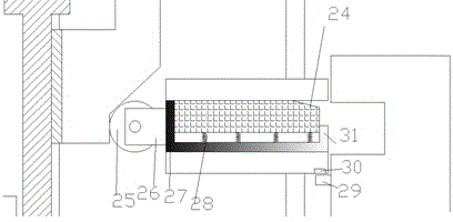
[0015] Combine below Figure 1-2 The present invention will be described in detail.

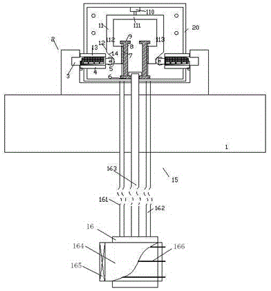
[0016] According to the present invention, the lifting device for building materials through fan heat dissipation includes a material basket 1, a locking assembly 20 and a lifting device 15, the material basket 1 is used to hold building materials, and the lifting device 15 is used to lift the material basket For lifting, the locking assembly can be fixed to the building body and can lock the position of the material basket in the raised position;

[0017] The lifting device 15 includes a lifting motor 16, a lifting screw 163 and two guide rods 161, 162, the lower end of the lifting screw 163 is power connected with the lifting motor 16, and the upper end is rotatable with the housing of the locking assembly 20 The lifting screw 163 is threadedly matched with the material basket 1 to lift it, and the two guide rods 161, 162 are fixedly connected to the housing of the locking assembly 20 and ...


PUM


Abstract

A building material lifting device cooled through a fan comprises a material basket (1), a locking assembly (20) and a lifting device (15). The material basket (1) is used for containing building materials, the lifting device (15) is used for ascending and descending the material basket, and the locking assembly can be fixed to a building and can lock the position of the material basket at an ascending position.

Description

technical field [0001] The invention belongs to the construction field, in particular to a building material lifting device that dissipates heat through a fan. Background technique [0002] In the construction industry, it is usually necessary to lift some building materials between floors to meet construction needs. The lifting of bulk building materials can be realized by special cranes. For small-scale material lifting, it is often realized by non-special equipment or even manpower, and its operation safety and reliability are relatively low. Contents of the invention [0003] The object of the present invention is to propose a building material lifting device that dissipates heat through a fan, which can safely and reliably lift building materials. [0004] According to the present invention, a building material lifting device that dissipates heat through a fan includes a material basket, a locking assembly, and a lifting device, the material basket is used to hold b...

Claims


Application Information

Patent Timeline
IPC IPC(8): B66B9/02B66B1/36B66B11/04B66B7/02
CPCB66B1/36B66B7/02B66B9/02B66B11/04
Inventor 余储
Owner 滁州现代建筑科技股份有限公司
Learn More