Supercharge Your Innovation With Domain-Expert AI Agents!

LED bulb lamp

A technology of LED bulb lamp and lamp body, which is applied in lighting devices, cooling/heating devices of lighting devices, light sources, etc., can solve the problem of affecting the appearance, increasing the cost, and the cross-sectional area of ​​the bulb lamp body and the lampshade. and other issues, to achieve the effect of increasing aesthetics, increasing surface area, and facilitating heat dissipation

Inactive Publication Date: 2015-04-22
ZHEJIANG WANSHENG PHOTOELECTRIC SCI TECH CO LTD
View PDF6 Cites 0 Cited by
  • Summary
  • Abstract
  • Description
  • Claims
  • Application Information

AI Technical Summary

Problems solved by technology

[0002] Since the appearance of LED lamps, how to dissipate heat better and faster has always been the main problem of people's research. At present, the lamp body of the LED lamps in the prior art mainly solves the problem of heat dissipation, and in some occasions, especially some entertainment places, It is particularly important to set some protective covers or personalized decorations on the lamp body, and because the cross-sectional area of ​​the lamp body and the lampshade is not much different for the bulb lamp, it is generally not possible to hang protective covers or lamp accessories on the lamp body itself. There are generally two ways to solve this problem with technology: 1. Hang the protective cover or decoration of the lamp on another pull wire to surround the lamp for protection or decoration; 2. Temporarily hang the protective cover or decoration on the lamp There are two main problems in this way. First, additional pull wires are needed to provide attachment points for the protective cover or decorations, which increases the cost and affects the appearance; second, temporarily hangs the protective cover or decorations on the lamps, which is time-consuming and laborious. , it is inconvenient to use, and it is easy to fall off, which has certain safety problems

Method used


Image

  • LED bulb lamp
  • LED bulb lamp
  • LED bulb lamp

Examples


Embodiment 1

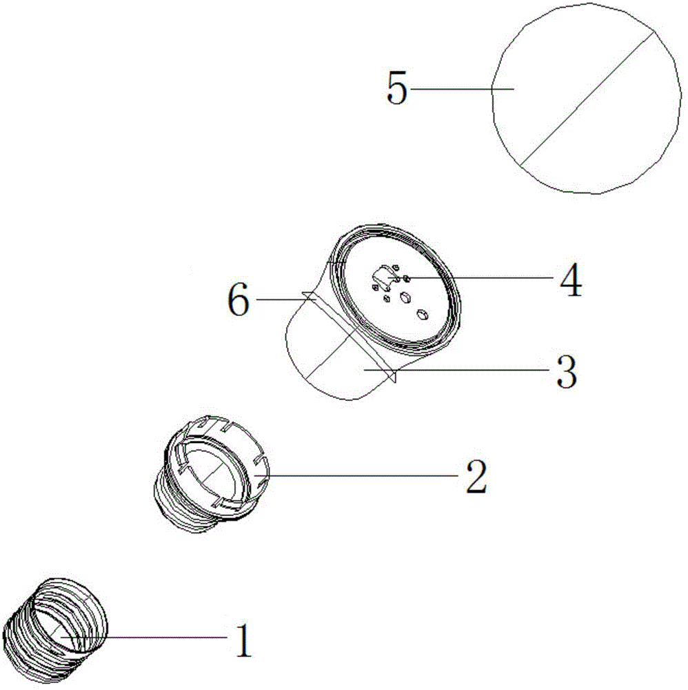
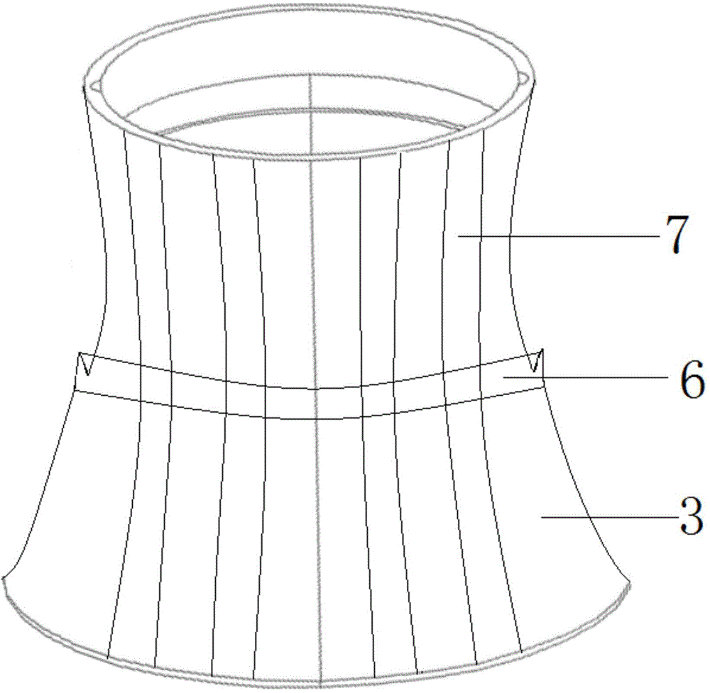
[0025] This embodiment discloses a LED bulb lamp, such as figure 1 , figure 2 As shown, it includes a bottom shell 1, a base 2, a lamp body 3, a light-emitting unit 4, and a lampshade 5. The bottom shell 1 is connected to the base 2 through threads, the lamp body 3 is a circular truncated structure, and the lamp holder 2 is connected to the lamp body 3 through threads. , the end of the lamp body 3 with a large cross-sectional area is a closed structure, the bottom of the closed structure of the lamp body 3 constitutes a bottom plate, the LED chip of the light-emitting unit 4 is arranged on the bottom plate, the lamp body 3 and the lampshade 5 are connected through a slot, and the lamp body 3 There is a circle of ring-shaped protrusions 6 on the outer periphery of the lamp body, and an injection molding layer 7 is formed on the outer surface. The ring-shaped protrusions 6 are reversely upward along the longitudinal direction of the lamp body, and are integrated with the lamp b...

Embodiment 2

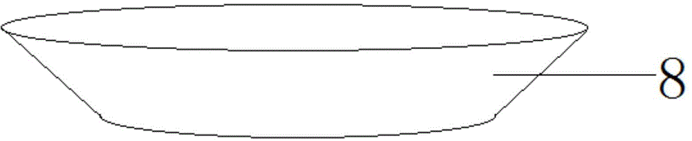
[0030] This embodiment discloses a LED bulb lamp, such as figure 1 , figure 2 , image 3 As shown, it includes a bottom shell 1, a base 2, a lamp body 3, a light-emitting unit 4, and a lampshade 5. The bottom shell 1 is connected to the base 2 through threads, the lamp body 3 is a circular truncated structure, and the lamp holder 2 is connected to the lamp body 3 through threads. , the end of the lamp body 3 with a large cross-sectional area is a closed structure, the bottom of the closed structure of the lamp body 3 constitutes a bottom plate, the LED chip of the light-emitting unit 4 is arranged on the bottom plate, the lamp body 3 and the lampshade 5 are connected through a slot, and the lamp body 3 There is a ring of annular protrusions 6 on the outer periphery of the lamp body, and the annular protrusions 6 are reversed upward along the longitudinal direction of the lamp body. The annular protrusions 6 are formed by covering the lamp body with a round platform 8 with an...

Embodiment 3

[0032] This embodiment discloses a LED bulb lamp, such as figure 1 , figure 2 , Figure 4 As shown, it includes a bottom shell 1, a base 2, a lamp body 3, a light-emitting unit 4, and a lampshade 5. The bottom shell 1 is connected to the base 2 through threads, the lamp body 3 is a circular truncated structure, and the lamp holder 2 is connected to the lamp body 3 through threads. , the end of the lamp body 3 with a large cross-sectional area is a closed structure, the bottom of the closed structure of the lamp body 3 constitutes a bottom plate, the LED chip of the light-emitting unit 4 is arranged on the bottom plate, the lamp body 3 and the lampshade 5 are connected through a slot, and the lamp body 3 There is a circle of ring-shaped projections 6 on the outer periphery of the lamp body, and the ring-shaped projections 6 are upward along the longitudinal direction of the lamp body.


PUM


Abstract

The invention discloses an LED bulb lamp, in particular to an LED bulb which is delicate in structure and capable of facilitating hanging of ornaments or protective covers. The LED bulb lamp comprises a bottom shell, a base, a lamp body, a light emitting unit and a lamp shade. The bottom shell is connected with the base through threads, the lamp body is of a circular-truncated-cone-shaped structure, the base is connected with the lamp body through threads, the end with the large cross sectional area of the lamp body is of a closed structure, a bottom plate is arranged at the bottom of the closed structure of the lamp body, an LED chip of the light emitting unit is arranged on the bottom plate, the lamp body and the lamp shade are connected through a slot, a circle of annular protrusion is arranged on the periphery of the lamp body and is reversely upward in the longitudinal direction of the lamp body, the protective cover or other ornaments can be directly hung on the lamp body conveniently, an injection molding layer is arranged on the outer surface of the lamp body, and attractiveness and safety can be improved.

Description

technical field [0001] The invention relates to an LED bulb lamp, in particular to an LED bulb lamp with a delicate structure and is convenient for hanging decorations or protective covers. Background technique [0002] Since the appearance of LED lamps, how to dissipate heat better and faster has always been the main problem of people's research. At present, the lamp body of the LED lamps in the prior art mainly solves the problem of heat dissipation, and in some occasions, especially some entertainment places, It is particularly important to set some protective covers or personalized decorations on the lamp body, and because the cross-sectional area of ​​the lamp body and the lampshade is not much different for the bulb lamp, it is generally not possible to hang protective covers or lamp accessories on the lamp body itself. There are generally two ways to solve this problem with technology: 1. Hang the protective cover or decoration of the lamp on another pull wire to surr...

Claims


Application Information

Patent Timeline
IPC IPC(8): F21S2/00F21V17/16F21V17/12F21V29/70F21Y101/02
CPCF21K9/232F21V17/12F21V17/164F21Y2101/00
Inventor 向昌强张顺来
Owner ZHEJIANG WANSHENG PHOTOELECTRIC SCI TECH CO LTD
Features
  • R&D
  • Intellectual Property
  • Life Sciences
  • Materials
  • Tech Scout
  • Unparalleled Data Quality
  • Higher Quality Content
  • 60% Fewer Hallucinations
Learn More