Hollow discharger for stirling cryocooler and vacuum air extraction device thereof

A vacuum pumping device and ejector technology, applied in refrigerators, refrigeration and liquefaction, compressors, etc., can solve the problems of cooling loss, reduce the thermal conductivity of the ejector, etc., to achieve easy operation, reduce heat conduction and heat leakage. Effect

A vacuum pumping device and ejector technology, applied in refrigerators, refrigeration and liquefaction, compressors, etc., can solve the problems of cooling loss, reduce the thermal conductivity of the ejector, etc., to achieve easy operation, reduce heat conduction and heat leakage. Effect

CN104534718AInactive Publication Date: 2015-04-22SHANGHAI INST OF TECHNICAL PHYSICS - CHINESE ACAD OF SCI

Image

  • Hollow discharger for stirling cryocooler and vacuum air extraction device thereof
  • Hollow discharger for stirling cryocooler and vacuum air extraction device thereof
  • Hollow discharger for stirling cryocooler and vacuum air extraction device thereof

Examples


Embodiment Construction

[0018] The present invention is further described below according to the accompanying drawings and embodiments.

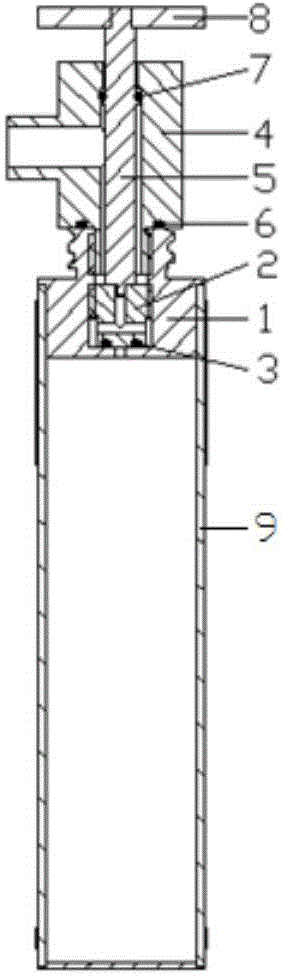
[0019] Such as figure 1 As shown, the vacuum pumping device of the hollow ejector of the Stirling refrigerator according to the present invention includes an improved ejector end cover 1, an ejector housing 9, a valve core 2, an air extraction valve seat 4, an air extraction valve Rod 5, valve stem handle 8, and three sealing rings 3, 6, 7. In the device, the spool 2 and the discharger end cover 1 are connected by threads, the sealing groove is opened at the bottom of the spool, and the sealing ring 1 is installed; the suction valve seat 4 is connected to the discharger end cover 1 by threads, and the suction valve seat 4 is connected to the The upper end surface of the device end cover 1 is provided with a sealing ring 2 6 for sealing, and the side opening of the exhaust valve seat 4 is connected to the vacuum pump; There is a sealing ring 37 to seal between the...


PUM


Abstract

The invention discloses a hollow discharger for a stirling cryocooler and a vacuum air extraction device thereof. The stirling cryocooler comprises an improved discharger end cover, a discharger casing, a valve element, an air extraction valve seat and an air extraction valve rod. The hollow discharger is applied to a regenerator and the stirling cryocooler of the discharger, the vacuumizing is conducted on the discharger, the vacuum degree is kept, and the heat conductivity of the discharger is effectively reduced. The valve element is in threaded connection with the discharger end cover, a sealing groove is formed in the bottom of the valve, and a sealing ring is installed. The air extraction valve seat is in threaded connection with the discharger end cover, sealing rings are installed on the upper end face of the air extraction valve and the discharger end cover, and a hole is formed in the side of the extraction valve and connected with a vacuum pump. One end of the air extraction valve is embedded in a straight slot in the top end of the valve element and used for screw the valve element out. A sealing ring is arranged between the air extraction valve rod and the air extraction valve seat for sealing. In the vacuumizing process, air in the discharger is extracted from a through hole of the valve element. After the vacuumizing process, the valve element is screwed tightly, the sealing ring is pressed tightly, and vacuum sealing in the discharger can be achieved.

Description


Claims


Application Information

Patent Timeline
22 Apr 2015
Publication
CN104534718A