Touch display panel and touch display device

A touch display panel, alternately arranged technology, applied in the direction of instruments, computing, electrical digital data processing, etc., can solve the problems affecting the visual effect, the touch pattern design of the touch display panel is obvious, etc., to improve the visual effect and good shadow disappearing effect Effect

Inactive Publication Date: 2015-04-22
BOE TECH GRP CO LTD +1
View PDF4 Cites 5 Cited by
  • Summary
  • Abstract
  • Description
  • Claims
  • Application Information

AI Technical Summary

Problems solved by technology

The inventors of this case found that the touch pattern design on the touch display panel is precisely because the strip electrode area and the spacer area in the existing layout design match themselves in terms of shape factors such as width and spacing or do not match each other. The texture is obvious, thus affecting the visual effect

Method used


Image

  • Touch display panel and touch display device
  • Touch display panel and touch display device
  • Touch display panel and touch display device

Examples


no. 1 Embodiment

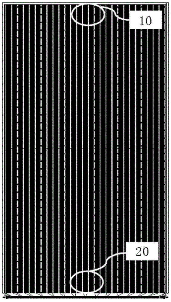
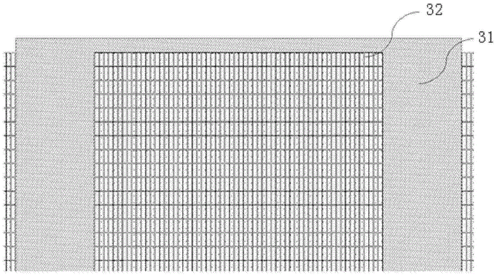
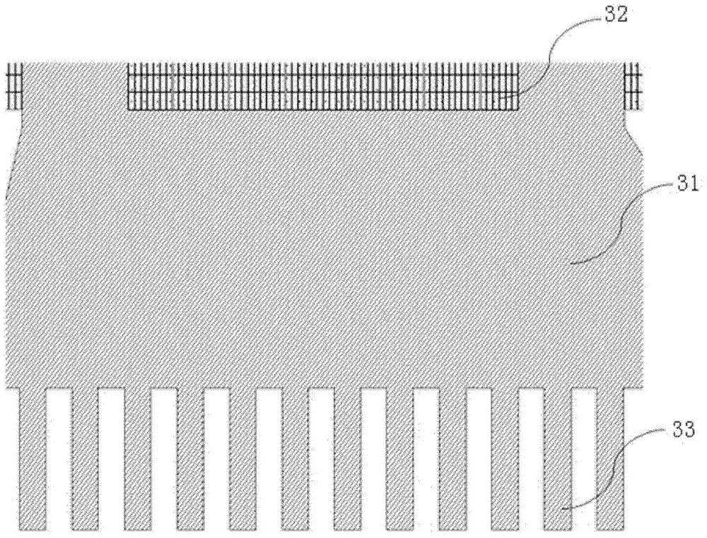
[0043] Figure 4 It is a display effect diagram of the entire touch effective area of ​​a touch display panel according to the first specific embodiment of the present invention; Figure 5 yes Figure 4 A detailed view of the portion marked A at the top of the touch pattern design in ; and Figure 6 yes Figure 4 Detail view of the portion labeled B at the lower end of the middle touch pattern design.

[0044] Such as Figure 4-6 In the first specific embodiment shown, the touch display panel includes Rx electrodes, and each Rx electrode has a strip-shaped electrode area 1 and a spacer area 2 . In this embodiment, each Rx electrode has a plurality of strip electrode regions 1 and a plurality of spacer regions 2 . Of course, in other embodiments, each Rx electrode may have single or multiple strip electrode regions and single or multiple spacer regions. Specifically, the touch display panel includes a plurality of strip-shaped electrode areas 1 and a plurality of spaced a...

no. 2 Embodiment

[0049] Figure 7 It is a detailed view of the part at the upper end of the entire touch pattern design of a touch display panel according to the second specific embodiment of the present invention; and Figure 8 It is a detailed view of the part at the lower end of the entire touch pattern design of a touch display panel according to the second specific embodiment of the present invention.

[0050] Such as Figure 7-8 In the second specific embodiment shown, the touch display panel includes Rx electrodes, and each Rx electrode has a strip electrode area 1' and a spacer area 2'. In this embodiment, each Rx electrode has a plurality of strip electrode regions 1' and a plurality of spacer regions 2'. Of course, in other embodiments, each Rx electrode may have single or multiple strip electrode regions and single or multiple spacer regions. Specifically, the touch display panel includes alternately arranged strip-shaped electrode areas 1' and spacer areas 2', each strip-shaped ...


PUM


Abstract

The invention provides a touch display panel capable of improving the visual effect. The touch display panel comprises at least one strip-shaped electrode region and at least one spacing region, which are arranged alternatively, wherein each strip-shaped electrode region comprises a plurality of strip-shaped signal lines distributed side by side, each spacing region comprises a plurality of spacers distributed side by side, each signal line and each spacer are the same in width, and a distance between each two adjacent signal lines in each strip-shaped electrode region is equal to a distance between each two adjacent spacers in each spacing region and is integer multiples of a distance among sub pixel units on the touch display panel. Accordingly, the invention also provides a touch display device provided with the touch display panel.

Description

technical field [0001] The present invention relates to the field of display technology, in particular to the layout design of touch patterns in a touch display panel, and a touch display device with the touch display panel. Background technique [0002] At present, the touch display panel has become the mainstream mobile display terminal configuration, and among them, the capacitive touch screen has an absolute advantage. Among various capacitive touch screens, a touch screen using a hybrid touch technology (hybrid in cell) has a very good prospect because of its good signal-to-noise ratio and compatibility with on-cell technology. Generally, in an existing touch screen using a hybrid in cell technology, the Tx electrodes are integrated in the liquid crystal cell, and the Rx electrodes are arranged outside the liquid crystal cell in the form of an ITO sensor. Specifically, the layout design of the Rx electrodes usually includes two parts: one part is a strip electrode (pro...

Claims


Application Information

Patent Timeline
Patent Type & Authority Applications(China)
IPC IPC(8): G06F3/041
CPCG06F3/0412G06F3/044G06F2203/04112
Inventor 龙跃黄炜贇王杨刘庭良
Owner BOE TECH GRP CO LTD
Why Eureka
Try Eureka