Adaptive floating combined cervical interbody fusion cage

An intervertebral cage and cage technology, applied in the field of intervertebral cages, can solve the problems of large surgical trauma, difficult operation, large surgical incision, etc., and achieve the effects of preventing random rotation, convenient screwing, and reducing pain.

Inactive Publication Date: 2015-04-29
范伟力
View PDF10 Cites 5 Cited by
  • Summary
  • Abstract
  • Description
  • Claims
  • Application Information

AI Technical Summary

Problems solved by technology

In previous operations, a single intervertebral fusion cage and a single steel plate were used for fixation. The intervertebral fusion cage was not fixed with the steel plate, and there was a risk of fusion cage displacement and non-fusion, resulting in surgical failure.
There is another kind of intervertebral fusion device. The steel plate and the fusion device are fixed together for use. The steel plate is provided with fixing holes, and the fusion device is fixed through the fixing holes and screws. Although this fixing method can better limit the space of the fusion device position, but when the steel plate and the fusion cage are installed, there is no relative floating space between the two, and it cannot be adjusted, resulting in the inability to ensure a close fit with the bone surface of the upper and lower adjacent cones, which seriously affects the surgical effect
In addition, fixing the steel plate on the fusion cage before implanting requires a larger surgical incision, which not only causes a large surgical trauma, but also is difficult to operate, which increases the pain of the patient

Method used


Image

  • Adaptive floating combined cervical interbody fusion cage
  • Adaptive floating combined cervical interbody fusion cage
  • Adaptive floating combined cervical interbody fusion cage

Examples


Embodiment 1

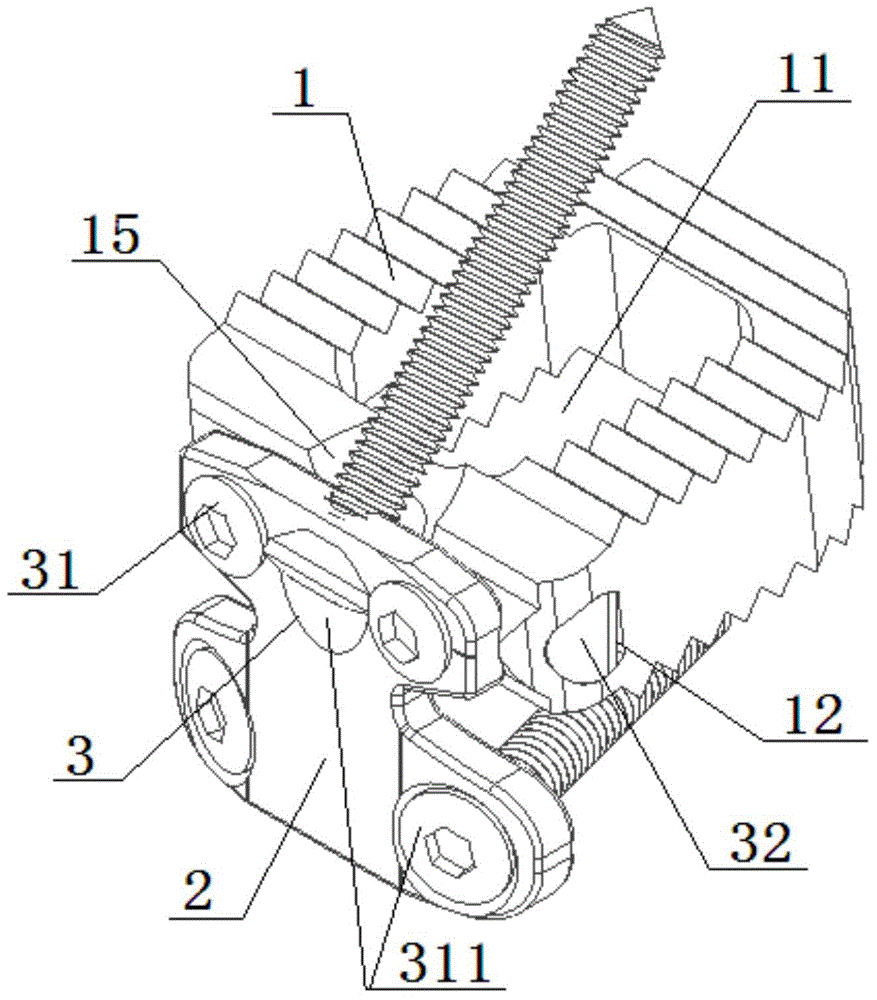
[0029] Please refer to figure 1 As shown, the preferred embodiment of the self-adaptive floating combination cervical intervertebral fusion device of the present invention includes: a fusion device body 1 , a steel plate 2 and a connection mechanism 3 , and the connection mechanism 3 includes two screws 31 and a rotating shaft 32 . The steel plate 2 is connected with the connecting mechanism 3, the fusion device main body 1 is movably fixed on the connecting mechanism 3, and the fusion device main body 1 and the steel plate 2 are fitted in an arc surface.

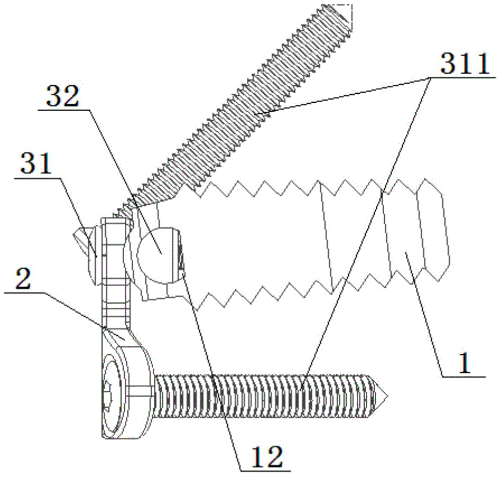
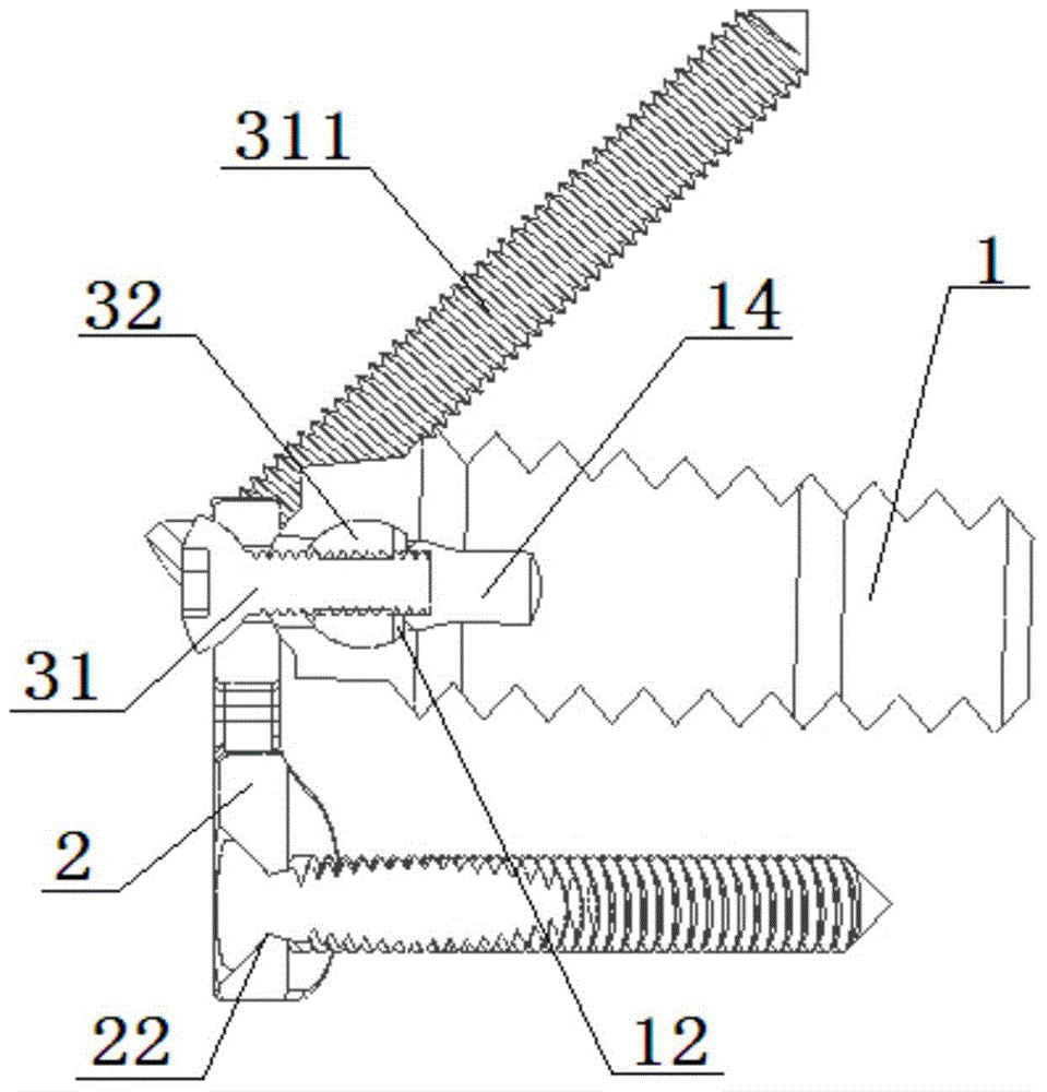
[0030] Please refer to figure 2 , image 3 and Figure 4 As shown, specifically, the fusion device main body 1 is provided with a fusion hole 11 through up and down, the fusion device main body 1 is divided into a fixed end and a movable end, and the left and right sides of the fixed end are provided with rotating holes 12, The rotating shaft 32 is movably disposed in the rotating hole 12 and the arc surface of the rota...

Embodiment 2

[0036] Please refer to Figure 8 As shown, another embodiment of the adaptive floating combination cervical intervertebral fusion device of the present invention includes: a fusion device body 1 , a steel plate 2 and a connecting mechanism 3 , and the connecting mechanism 3 includes two screws 31 . The steel plate 2 is connected with the connecting mechanism 3, the fusion device main body 1 is movably fixed on the connecting mechanism 3, and the fusion device main body 1 and the steel plate 2 are fitted in an arc surface.

[0037] Please refer to Figure 9 and Figure 10 As shown, specifically, the fusion device body 1 is provided with a fusion hole 11 through up and down, the fusion device body 1 is divided into a fixed end and a movable end, and the end surface of the fixed end of the fusion device body 1 is directed toward An arc-shaped convex strip 13 protruding outward, an arc-shaped groove 21 matching the arc-shaped convex strip 13 is provided on the inner side of the ...

Embodiment 3

[0043] This embodiment is changed on the basis of Embodiment 1, and two screws 31 are changed into one screw 31, and correspondingly, one hole is provided for each screw 31 to pass through. Other connections are the same as in Embodiment 1.


PUM


Abstract

The invention discloses an adaptive floating combined cervical interbody fusion cage comprising a cage body, a steel plate and a connection mechanism. The steel plate is connected to the connection mechanism, the cage body is movably fixed to the connection mechanism, and the cage body and the steel plate are in arc matching. The steel plate and the cage body are connected in a floating manner, the fusion cage can be adjusted according to the implant position, the adjacent cervical surfaces are fitted tightly, a screw between the steel plate and the cage body is screwed after the implantation, the incision is small, and the operation difficulty is low.

Description

technical field [0001] The invention relates to an intervertebral fusion device, in particular to an adaptive floating combination cervical intervertebral fusion device. Background technique [0002] Cervical spondylotic myelopathy and cervical spondylotic radiculopathy are common and frequently-occurring diseases of middle-aged and elderly people. With the change of lifestyle, the incidence rate is also increasing year by year, and it shows a younger trend. The pathogenic mechanism of cervical spondylosis is that the cervical intervertebral disc protrudes backward after the degeneration, or the posterior edge of the pyramidal bone hyperplasia forms osteophytes that compress the spinal cord and nerve roots in the cervical spinal canal. Because the nerve cells in the spinal cord tissue are very fragile, the compression causes The loss of nerve function caused by pathological changes such as ischemia and hypoxia is irreversible. Therefore, early surgical treatment should be p...

Claims


Application Information

Patent Timeline
Patent Type & Authority Applications(China)
IPC IPC(8): A61F2/44A61B17/70
Inventor 范伟力
Owner 范伟力
Why Eureka
Try Eureka