Clamp for cleaning cavity of air brake control valve middle body

An air braking and cleaning fixture technology, applied in cleaning methods and appliances, cleaning methods using liquids, chemical instruments and methods, etc., can solve problems such as difficult sealing, achieve convenient operation, stable sealing performance, and simple clamping process Effect

Inactive Publication Date: 2015-04-29
CRRC GUIYANG CO LTD
View PDF0 Cites 3 Cited by
  • Summary
  • Abstract
  • Description
  • Claims
  • Application Information

AI Technical Summary

Problems solved by technology

[0003] The purpose of the present invention is to provide a simple structure, convenient operation, convenient clamping, good sealing performance, solve the sealing difficulties caused by the difference in size and shape of different valve bodies, realize floating clamping and sealing, and improve the cleaning time of intermediates. Clamping step work efficiency, and then improve the intermediate body cleaning efficiency and quality of an air brake control valve intermediate cavity cleaning fixture to overcome the deficiencies of the prior art

Method used


Image

  • Clamp for cleaning cavity of air brake control valve middle body
  • Clamp for cleaning cavity of air brake control valve middle body
  • Clamp for cleaning cavity of air brake control valve middle body

Examples


Embodiment Construction

[0012] The present invention will be further described in detail below in conjunction with the accompanying drawings and embodiments.

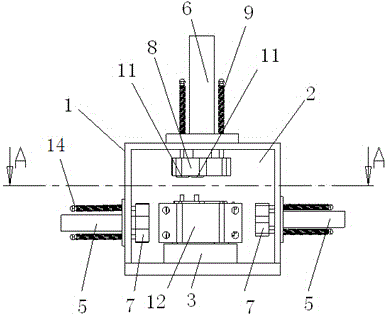
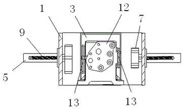
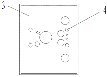
[0013] Embodiment of the present invention: a fixture for cleaning the inner cavity of an air brake control valve, including a cleaning chamber shell 1 and a cleaning chamber 2 formed inside the cleaning chamber shell 1, and a base 3 is provided at the bottom of the cleaning chamber (2). The base 3 is provided with a placement hole 4 corresponding to the bolt on the intermediate body of the air brake control valve, and the side hydraulic cylinder 5 and the top hydraulic cylinder 6 are respectively provided on the left and right sides and the top of the cleaning chamber shell 1. In the chamber 2 and at the ends of the piston rods of the side hydraulic cylinder 5 and the top hydraulic cylinder 6, a side seal cover 7 and a top seal cover 8 are arranged, and the side seal cover 7 and the top seal cover 8 are connected with the end of the correspond...


PUM


Abstract

The invention discloses a clamp for a cleaning cavity of an air brake control valve middle body. The clamp comprises a cleaning chamber shell and a cleaning chamber formed in the cleaning chamber shell, wherein a foundation is arranged at the bottom of the cleaning chamber; a placing hole corresponding to a bolt on the air brake control valve middle body is formed in the foundation; side hydraulic oil cylinders and a top hydraulic oil cylinder are respectively arranged on the left side, the right side and the top of the cleaning chamber shell; side sealing covers and a top sealing cover are respectively arranged at one end of piston rods of each of the side hydraulic oil cylinders and the top hydraulic oil cylinder; a reset spring is arranged on each of the side sealing covers and the top sealing cover; a conical positioning hole is formed in each of the side sealing covers and the top sealing cover. The clamp has the advantages of simple structure and convenience in operation, is capable of eliminating size error, and satisfies the cleaning requirement of middle bodies from different factories, the sealing property is stable, and a clamping process is simple, quick and safe.

Description

technical field [0001] The invention relates to a jig for cleaning the internal cavity of an air brake control valve intermediate, and belongs to the technical field of cleaning the internal cavity of a railway vehicle air valve valve. Background technique [0002] At present, the air brake control valve (120 valve) for railway freight cars is the control center and core component of the freight car brake. The production and maintenance quality of the 120 valve directly affects the safety of railway operation. There are also many accessories, many air passages and the aperture is small, the smallest diameter is only ∮0.2mm, so if the dirt, sludge and other sundries formed during the production and use of the valve are not completely removed, it is easy to block the brake. The air channel causes brake failure and brings serious hidden dangers to the safety of railway wagons. The existing cleaning method is to place the air brake control valve in a special cleaning device and ...

Claims


Application Information

Patent Timeline
Patent Type & Authority Applications(China)
IPC IPC(8): B08B3/00B08B13/00
CPCB08B13/00
Inventor 代顺生钟柯章寅寅
Owner CRRC GUIYANG CO LTD
Why Eureka
Try Eureka