One-mold two-part injection mold

A technique for injection molds and fixed molds, which is applied in the field of one-piece two-piece injection molds, can solve problems such as difficulty in maintaining consistency, and achieve the effect of consistent color and texture

Active Publication Date: 2015-04-29
浙江世纪华通车业有限公司
View PDF4 Cites 1 Cited by
  • Summary
  • Abstract
  • Description
  • Claims
  • Application Information

AI Technical Summary

Problems solved by technology

However, in the existing technology, two different plastic parts usually require two different sets of molds for injection molding, and the color and texture of the plastic parts will b

Method used


Image

  • One-mold two-part injection mold
  • One-mold two-part injection mold
  • One-mold two-part injection mold

Examples


Embodiment Construction

[0036] The present invention is further described in conjunction with the following examples.

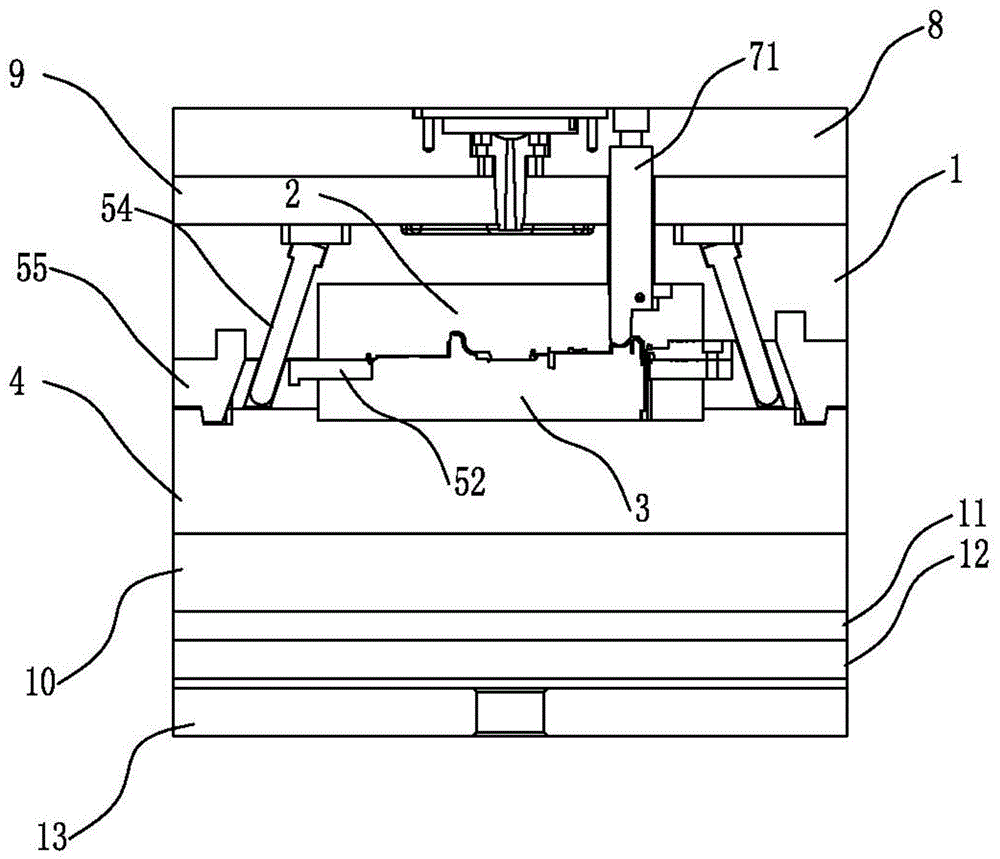
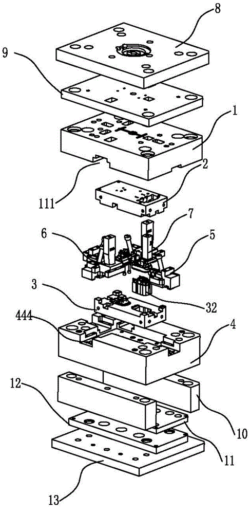
[0037] The one-die two-piece injection mold that the present invention creates, as figure 1 with figure 2 As shown, it includes fixed mold bottom plate 8, stripper plate 9, fixed mold plate 1, fixed mold core 2, movable mold core 3, movable mold plate 4, square iron 10, face needle plate 11, bottom needle plate 12 and movable mold plate arranged in sequence. A first row assembly 5 , a second row assembly 6 and a third row assembly 7 are arranged between the mold bottom plate 13 , the fixed template 1 and the movable template 4 .

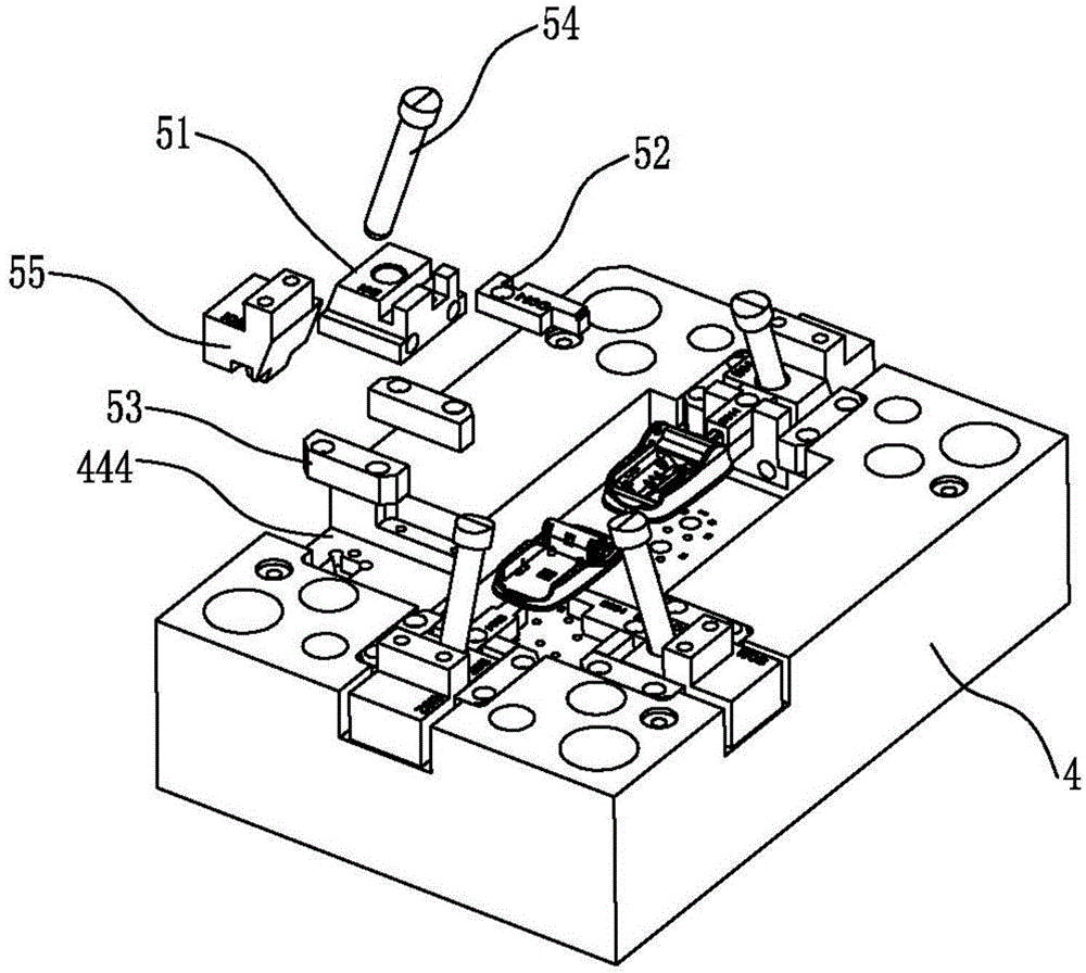
[0038] Such as Figure 7 As shown, a first cavity 21 and a second cavity 22 are arranged side by side on the fixed mold core 2, as Image 6 As shown, the first core 31 and the second core 32 respectively corresponding to the first cavity 21 and the second cavity 22 are arranged side by side on the movable mold core 3, preferably, the second core 32 and...


PUM


Abstract

The invention relates to the technical field of molds and in particular relates to a one-mold two-part injection mold. The injection mold comprises a fixed mold bottom plate, a stripper plate, a fixed mold plate, a fixed mold core, a movable mold core, a movable mold plate, square iron, an ejector retainer plate, an ejector base plate and a movable mold bottom plate, wherein a first row orientation component, a second row orientation component and a third row orientation component are arranged between the fixed mold plate and the movable mold plate; a first cavity and a second cavity are arranged on the fixed mold core in parallel; and a first core and a second core which are correspondingly molded with the first cavity and the second cavity are respectively arranged on the movable mold core in parallel. According to the one-mold two-part injection mold, two injection parts which are similar in shape structure and are assembled in a matched mode are simultaneously molded, so that the colors and textures of the two injection parts can be consistent as far as possible.

Description

technical field [0001] The invention relates to the technical field of moulds, in particular to a two-piece injection mould. Background technique [0002] With the improvement of consumption level, consumers not only pay more attention to the quality of housings of electronic products, but also pay more and more attention to their appearance. Most of the existing electronic products still use plastic shells, and generally need to be assembled by combining at least two plastic parts. There are large differences between them, and will be regarded as low-end products. Naturally, it is not easy to win the favor of consumers, thus losing market competitiveness. Facing the increasingly fierce market competition, electronic product manufacturers have to make further pursuit of the appearance quality of their products in order to improve the competitiveness of their own products and improve the level of products. However, in the existing technology, two different plastic parts usu...

Claims


Application Information

Patent Timeline
IPC IPC(8): B29C45/32B29C45/33
CPCB29C45/0025B29C45/32B29C45/33
Inventor 申富林
Owner 浙江世纪华通车业有限公司
Why Eureka
Try Eureka