Eureka AIR delivers breakthrough ideas for toughest innovation challenges, trusted by R&D personnel around the world.

Compression mechanism and compressor provided with same

A technology of compression mechanism and compression chamber, applied in the field of compression mechanism and compressor, can solve the problems of affecting the suction volume of the pump body, the energy lost in work, and the performance of the compressor, so as to improve the volumetric efficiency and product performance, and reduce noise. Vibration, the effect of reducing power consumption

Inactive Publication Date: 2015-04-29
GUANGDONG MEIZHI COMPRESSOR
View PDF6 Cites 5 Cited by
  • Summary
  • Abstract
  • Description
  • Claims
  • Application Information

AI Technical Summary

Problems solved by technology

[0002] Rotary compressors generally use upper bearing exhaust or upper and lower bearing exhaust. Rotary compressors belong to the exhaust valve seat and the exhaust valve plate cooperate with exhaust, and there is a large clearance volume, mainly including the upper bearing exhaust port. The volume and the volume of the oblique cutout of the cylinder lead to the backflow of the clearance and the backflow of the valve (there are two backflows of the valve, the first backflow when the valve piece is not completely closed during the falling process; the impact rebound after the valve piece falls, and the second backflow caused by reopening Influenced by flow), the compressor fails to discharge the gas completely, and the high-pressure gas left not only loses the energy of doing work, but also affects the suction volume of the next pump body, causing the performance of the compressor to decline

Method used


Image

  • Compression mechanism and compressor provided with same
  • Compression mechanism and compressor provided with same
  • Compression mechanism and compressor provided with same

Examples


Embodiment Construction

[0031] Embodiments of the present invention are described in detail below, examples of which are shown in the drawings, wherein the same or similar reference numerals designate the same or similar elements or elements having the same or similar functions throughout. The embodiments described below by referring to the figures are exemplary and are intended to explain the present invention and should not be construed as limiting the present invention.

[0032] In describing the present invention, it is to be understood that the terms "central", "longitudinal", "transverse", "length", "width", "thickness", "upper", "lower", "vertical", The orientation or positional relationship indicated by "horizontal", "top", "bottom", "inner", "outer", "clockwise", "counterclockwise", etc. are based on the orientation or positional relationship shown in the drawings, and are only In order to facilitate the description of the present invention and simplify the description, it does not indicate ...


PUM


Abstract

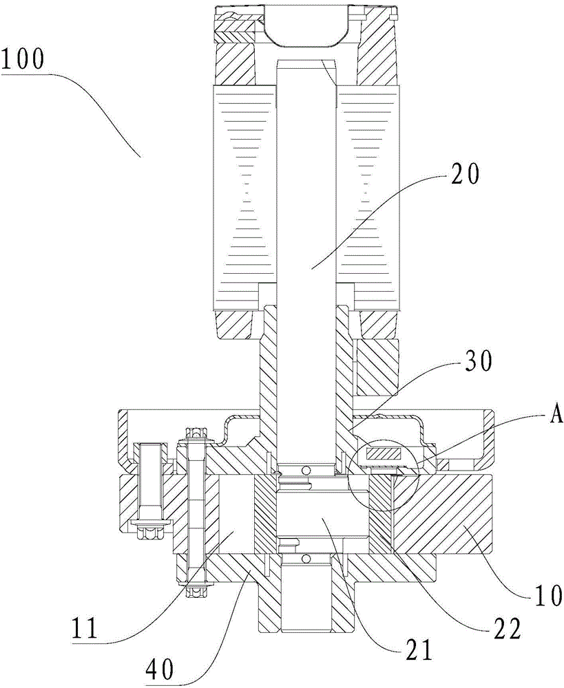
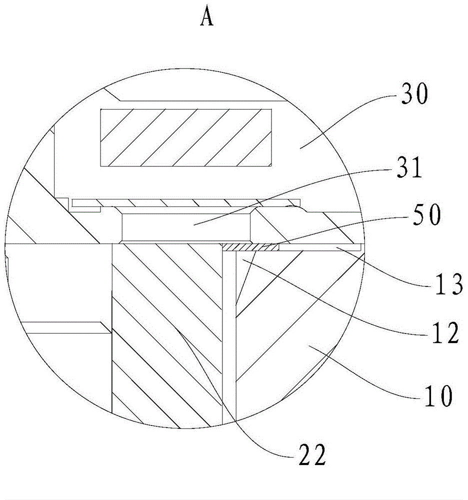
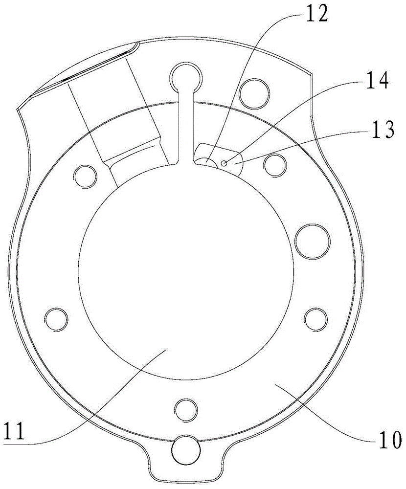
The invention discloses a compression mechanism and a compressor provided with the compression mechanism. The compression mechanism comprises a cylinder, a crankshaft, an upper bearing, a lower bearing and a switch valve plate, wherein a compression chamber is defined in the cylinder, and a tapered cut communicated with the compression chamber is formed in the upper end or the lower end of the inner wall surface of the cylinder; the crankshaft penetrates through the compression chamber along the axial direction of the cylinder and can rotate around the central axis of the crankshaft, the part, extending into the compression chamber, of the crankshaft is provided with an eccentric shaft, and a roller is arranged on the eccentric shaft; the upper bearing and the lower bearing are arranged at the upper end and the lower end of the cylinder respectively, and an exhaust hole corresponding to the tapered cut in position is formed in the upper bearing or the lower bearing and is connected with the tapered cut; and the switch valve plate is arranged between the upper end of the cylinder and the upper bearing or between the lower end of the cylinder and the lower bearing, and can move between a first position and a second position to connect or disconnect the tapered cut and the exhaust hole, the tapered cut is connected with the exhaust hole when the switch valve plate is at the first position, and the tapered cut is disconnected with the exhaust hole when the switch valve plate is at the second position.

Description

technical field [0001] The present invention relates to the technical field of refrigeration equipment, and more specifically, to a compression mechanism and a compressor having the same. Background technique [0002] Rotary compressors generally use upper bearing exhaust or upper and lower bearing exhaust. Rotary compressors belong to the exhaust valve seat and the exhaust valve plate cooperate with exhaust, and there is a large clearance volume, mainly including the upper bearing exhaust port. The volume and the volume of the oblique cutout of the cylinder lead to the backflow of the clearance and the backflow of the valve (there are two backflows of the valve, the first backflow when the valve piece is not completely closed during the falling process; the impact rebound after the valve piece falls, and the second backflow caused by reopening Influenced by flow), the compressor fails to discharge the gas completely, and the high-pressure gas left not only loses the energy ...

Claims


Application Information

Patent Timeline
Patent Type & Authority Applications(China)
IPC IPC(8): F04C29/12F04C29/06F04C18/356
Inventor 陈振华赖化鸿
Owner GUANGDONG MEIZHI COMPRESSOR
Why Eureka
Eureka Blog
Learn More