Rotary type compressor exhaust apparatus

A rotary compressor and exhaust device technology, applied in the field of compressors, can solve the problems of reduced compressor efficiency, achieve the effects of reducing clearance volume, reducing noise, and expanding exhaust area

Inactive Publication Date: 2005-06-29
LG ELECTRONICS (TIANJIN) APPLIANCES CO LTD
View PDF0 Cites 5 Cited by
  • Summary
  • Abstract
  • Description
  • Claims
  • Application Information

AI Technical Summary

Problems solved by technology

However, the larger the diameter, the larger the clearance volume, resulting in lower compressor efficiency

Method used


Image

  • Rotary type compressor exhaust apparatus
  • Rotary type compressor exhaust apparatus
  • Rotary type compressor exhaust apparatus

Examples


Embodiment Construction

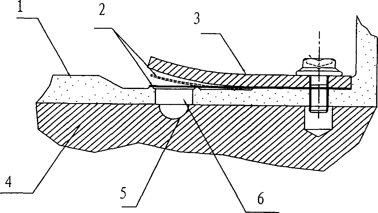
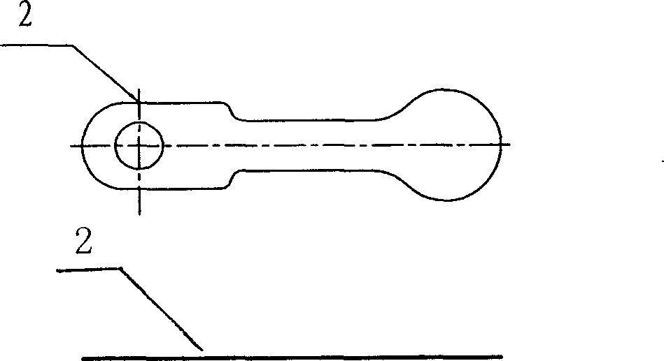
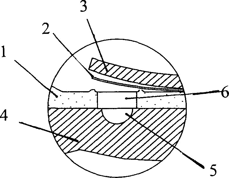
[0018] The present invention will be described in further detail below in conjunction with the accompanying drawings and specific embodiments: including compressor main bearing 1, stopper 3, compressor cylinder 4, cylinder exhaust hole 5, partial spherical exhaust valve plate 7 and conical row The air hole 8, the above-mentioned compressor main bearing 1 is fixed on the compressor cylinder 4, and the compressor cylinder 4 is provided with a cylinder exhaust hole 5, and the above-mentioned partial spherical exhaust valve plate 7 is fixed on the compressor main bearing 1. The main bearing 1 of the compressor is provided with a conical exhaust hole 8, the local spherical shape of the partial spherical exhaust valve plate 7 is aligned with the conical exhaust hole 8, and the above-mentioned limiter 3 is set on the partial spherical exhaust valve plate 7, fixed on the compressor main bearing 1.

[0019] In order to reduce the exhaust loss of the compressor and minimize the clearanc...


PUM


Abstract

The invention provides a rotary compressor exhaust device, which includes a compressor main bearing, a stopper, a compressor cylinder, a cylinder exhaust hole, a partially spherical exhaust valve plate and a conical exhaust hole. The main bearing is fixed on the compressor cylinder, and the compressor cylinder is provided with a cylinder exhaust hole. The above-mentioned partial spherical exhaust valve plate is fixed on the compressor main bearing, and a conical exhaust hole is arranged on the compressor main bearing. The local sphere of the partially spherical exhaust valve plate is aligned with the conical exhaust hole, and the above-mentioned limiter is arranged on the upper surface of the partially spherical exhaust valve plate and fixed on the main bearing of the compressor. The beneficial effects of the present invention are: the cylindrical exhaust hole is designed as a conical exhaust hole, which expands the exhaust area under the same circumstances, relatively reduces the clearance volume caused by the existence of the exhaust hole, and improves Improve the volumetric efficiency of the compressor and reduce noise.

Description

technical field [0001] This invention relates to compressors, and more particularly to rotary compressor dischargers. Background technique [0002] In the compressor structure of the prior art, the internal exhaust system is mainly composed of: compressor main bearing 1, exhaust valve plate 2, limiter 3, compressor cylinder 4, etc., the refrigerant gas in the compression chamber is compressed to a certain After a certain degree, the valve plate 2 is bounced up through the exhaust hole 5 of the cylinder and the exhaust hole 6 of the main bearing, so that the high-pressure refrigerant is discharged. FIG. 1 shows the related exhaust system structure of a compressor in the prior art. A cylindrical exhaust hole 6 is provided on the main bearing, and a flat plate valve plate 2 is provided to cover and seal the exhaust hole 6 . The larger the exhaust hole 6 diameter, the better the exhaust effect. However, the larger the diameter, the larger the clearance volume, resulting in low...

Claims


Application Information

Patent Timeline
Patent Type & Authority Applications(China)
IPC IPC(8): F04C29/00F04C29/06
Inventor 张旭田志强河宗勋
Owner LG ELECTRONICS (TIANJIN) APPLIANCES CO LTD
Why Eureka
Try Eureka