Movable valve base plate

A movable bottom plate technology, which is applied in the direction of sliding valves, valve devices, engine components, etc., can solve the problems such as difficult to clean dust and affect the air leakage coefficient of valves, and achieve the effect of solving easy dust accumulation, maintaining air leakage coefficient and prolonging service life

Inactive Publication Date: 2015-04-29
范永禧
View PDF0 Cites 0 Cited by
  • Summary
  • Abstract
  • Description
  • Claims
  • Application Information

AI Technical Summary

Problems solved by technology

[0004] The purpose of the present invention is to provide a movable valve bottom plate, which aims to solve the problem that the existing gate valve is difficult to clean the dust accumulated at the bottom of the valve due to its closed structure, and long-term use will greatly affect the air leakage of the valve. coefficient problem

Method used


Image

  • Movable valve base plate
  • Movable valve base plate

Examples


Embodiment Construction

[0013] In order to make the object, technical solution and advantages of the present invention more clear and definite, the present invention will be further described in detail below with reference to the accompanying drawings and examples.

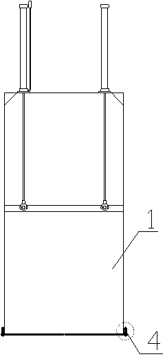
[0014] Such as figure 1 As shown, it is a structural schematic diagram of a movable valve bottom plate in the present invention, including a valve 1, a fixed bottom plate 2 and a sealing bottom plate 3: the fixed bottom plate 2 is fixedly connected to the bottom of the valve 1; the sealing bottom plate 3 is movably connected to the fixed bottom plate 2 below.

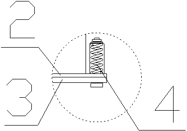
[0015] Such as figure 2 As shown, in this embodiment, the fixed bottom plate 2 is connected to the bottom of the valve 1 by welding; the fixed bottom plate 2 and the sealing bottom plate 3 are connected by bolts, and springs are sleeved on the bolts.

[0016] There are multiple bolts 3 covered with springs; in order to facilitate the discharge of dust, the bolts 3 are evenly ar...


PUM


Abstract

The invention discloses a movable valve base plate which comprises a fixed base plate fixedly arranged at the bottom of the valve and a sealing base plate movably connected below the fixed base plate. The fixed base plate and the sealing base plate are connected through a bolt. A spring sleeves the bolt. The movable base plate moves vertically by means of stretching of the spring. The bottom of a valve is changed to be in movable connection. The problem of ash accumulation at the bottom of the valve is solved, the air leakage coefficient of the valve is maintained, and the service life of the valve is prolonged.

Description

technical field [0001] The invention relates to a movable valve bottom plate. Background technique [0002] The existing gate valve has a closed structure. If the gate valve is installed on a pipeline with a large amount of dust, dust will easily accumulate at the bottom of the valve. Because of its closed structure, it is difficult to clean the accumulated dust. Long-term use will Will greatly affect the leakage coefficient of the valve. [0003] Therefore, the prior art still needs to be improved and developed. Contents of the invention [0004] The purpose of the present invention is to provide a movable valve bottom plate, which aims to solve the problem that the existing gate valve is difficult to clean the dust accumulated at the bottom of the valve due to its closed structure, and long-term use will greatly affect the air leakage of the valve. coefficient problem. [0005] Technical scheme of the present invention is as follows: [0006] A movable valve bottom p...

Claims


Application Information

Patent Timeline
Patent Type & Authority Applications(China)
IPC IPC(8): F16K3/314
CPCF16K3/30
Inventor 范永禧
Owner 范永禧
Why Eureka
Try Eureka