Heat pump unit

A technology of heat pump units and components, which is applied in heat pumps, refrigerators, refrigeration components, etc., can solve the problems of insufficient cooling capacity of the return water of the primary network, limited heat of the condenser, and increased volume of the unit, achieving reasonable structure and reduced volume , small size effect

Active Publication Date: 2018-11-13
GREE ELECTRIC APPLIANCES INC
View PDF4 Cites 0 Cited by
  • Summary
  • Abstract
  • Description
  • Claims
  • Application Information

AI Technical Summary

Problems solved by technology

[0004] The technical problem of the above scheme is: when using a simple absorption cycle, single-stage heat pump heat exchange unit, when the water supply temperature of the primary network is low (such as 100-120°C), the return water temperature of the primary network can only be reduced to 30°C. ℃; that is, the cooling capacity of the return water of the primary network is insufficient, and the heat recovered from the condenser at the heat source is limited
The use of a compound heat exchange unit requires an absorption heat pump and a compression heat pump to be connected in series, resulting in an increase in unit size and cost

Method used


Image

  • Heat pump unit
  • Heat pump unit
  • Heat pump unit

Examples


Embodiment 1

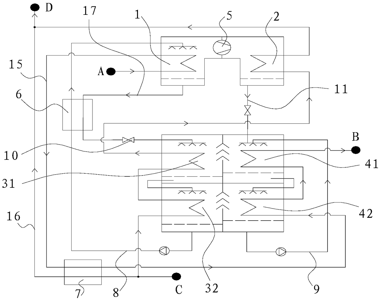
[0024] This preferred embodiment discloses a heat pump unit. Such as figure 1 As shown, the heat pump unit includes a generator 1 and a condenser 2 arranged adjacently, and an absorber assembly and an evaporator assembly adjacently arranged. Wherein, a water vapor compressor 5 is arranged between the generator 1 and the condenser 2; the absorber assembly includes a first absorber 31 and a second absorber 32 connected in series, and the first absorber 31 and the second absorber 32 The pipes are connected to form a passage, and the shells of the first absorber 31 and the second absorber 32 are communicated; the evaporator assembly includes a first evaporator 41 and a second evaporator 42 connected in series, and the first evaporator 41 and the second evaporator The pipes of the second evaporator 42 are connected to form a channel, the shells of the first evaporator 41 and the second evaporator 42 are connected, and a refrigerant water circulation pipeline 9 is provided.

[002...

Embodiment 2

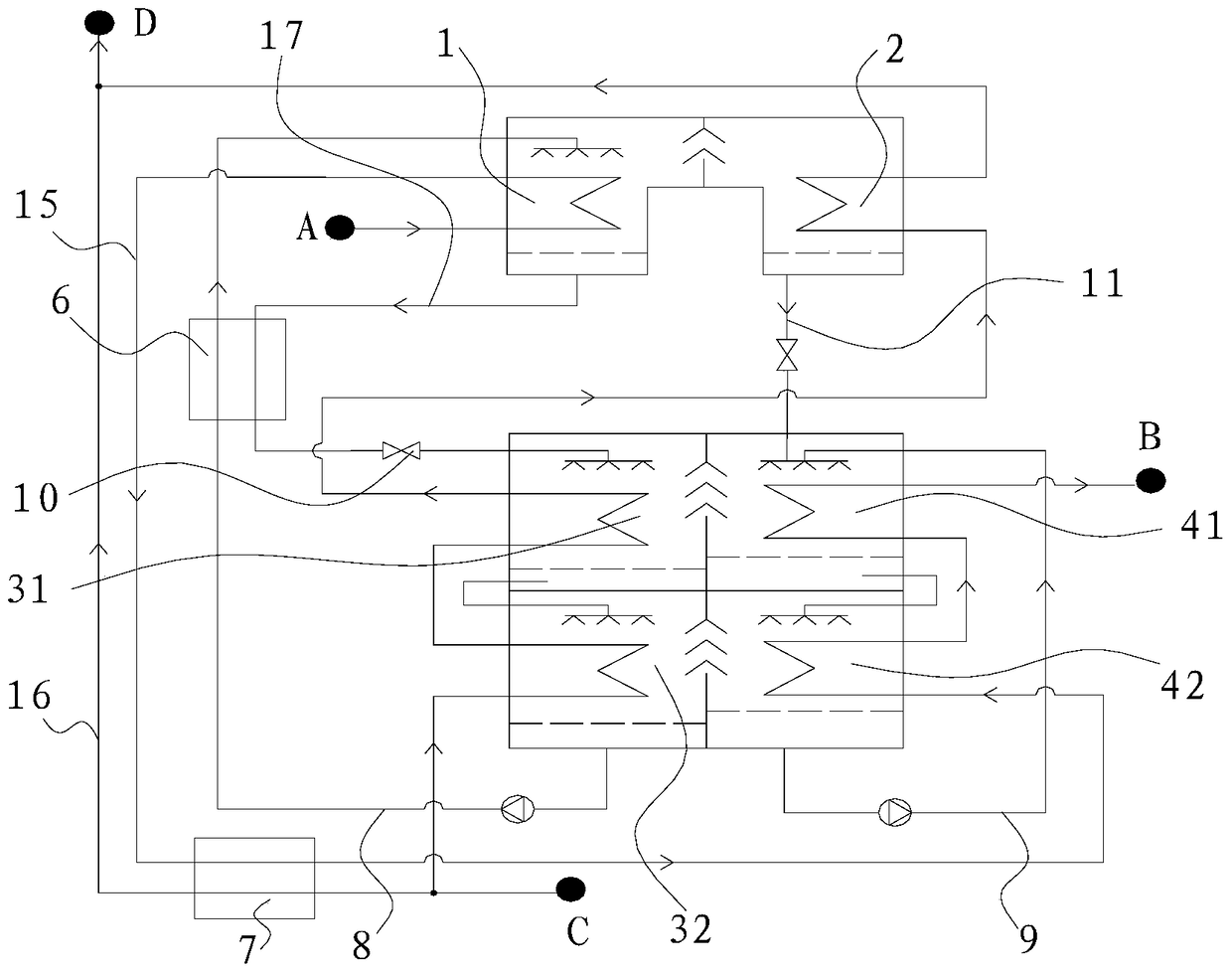
[0033] This preferred embodiment discloses a heat pump unit whose structure and working method are basically the same as those of the first preferred embodiment. The difference is that: if figure 2As shown, there is no steam compressor 5 between the generator 1 and the condenser 2 . In operation, the aqueous solution in the housing of the generator 1 evaporates to form water vapor which enters directly into the housing of the condenser 2 .

Embodiment 3

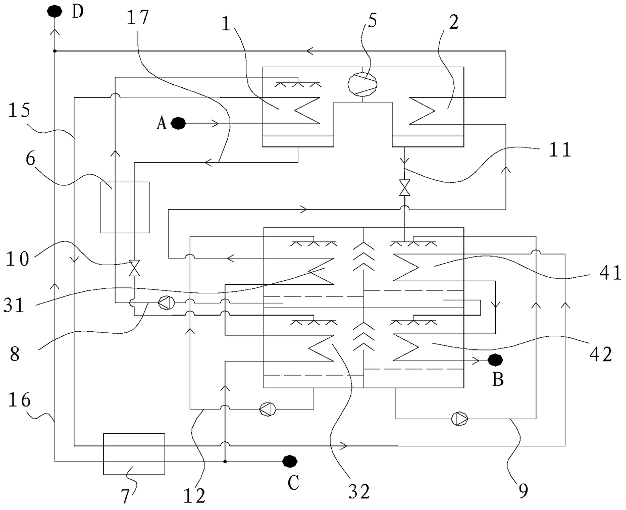
[0035] This preferred embodiment discloses a heat pump unit whose structure and working method are basically the same as those of the first preferred embodiment. The difference is that: if image 3 As shown, the shell of the second absorber 32 is connected to the shell of the first absorber 31 through the solution circulation pipeline 12, and the first branch 8 of the solution is connected between the shell of the generator 1 and the shell of the first absorber 31, The solution second branch 17 is connected between the shell of the generator 1 and the shell of the second absorber 32; the primary water pipe 15 is connected to the outlet end of the pipeline of the generator 1 and the pipeline inlet end of the first evaporator 41, and the primary water outlet B is provided at the pipe outlet end of the second evaporator 42 .

[0036] Correspondingly, the difference in the working method is: the solution in the shell of the second absorber 32 heats the secondary water in the pipe...


PUM


Abstract

The invention discloses a heat pump unit, and belongs to the field of heat and electricity co-production centralized heat supply systems, which aims at solving the problems of insufficient return water temperature lowering and the like of a loop network of the existing device. The heat pump unit comprises a generator, a condenser, an absorber assembly and an evaporator assembly, wherein the generator and the condenser are adjacently arranged, the absorber assembly and the evaporator assembly are adjacently arranged, the pipeline outlet end of the generator is connected with a primary water pipe, the primary water pipe penetrates through a water-water heat exchanger and is connected with the pipeline inlet end of the evaporator assembly, the pipeline inlet end of the absorber assembly is connected with a secondary water inlet C, a pipeline outlet of the absorber assembly is connected with a pipeline inlet of the condenser, a pipeline outlet of the condenser is connected with a secondary water outlet D, a secondary water pipe is arranged between the secondary water inlet C and the secondary water outlet D and penetrates through the water-water heat exchanger, and the secondary water pipe and the primary water pipe are adjacently arranged in the water-water heat exchanger. The heat pump unit has the advantage that the efficiency of the heat and electricity co-production centralized heat supply system is improved.

Description

technical field [0001] The invention relates to a heat pump unit. Background technique [0002] Combined heat and power central heating system is widely used in the heating of cities and towns in northern my country. In order to recover the condensation heat at the cogeneration heat source for heating and improve the efficiency of the cogeneration system, it is necessary to reduce the return water temperature of the primary network in the central heating system. [0003] In order to meet this requirement, the existing technologies include: 1. Install absorption heat pump units in each thermal station of the heating network to reduce the temperature of the return water of the primary network, and then recover the heat of the condenser in the power plant to heat the return water of the primary network; 2. Reduce the return water temperature of the primary network at each thermal station of the heat network; 3. Further reduce the return water temperature of the primary network...

Claims


Application Information

Patent Timeline
Patent Type & Authority Patents(China)
IPC IPC(8): F25B30/04
CPCY02P80/15
Inventor 刘华王升张治平
Owner GREE ELECTRIC APPLIANCES INC
Why Eureka
Try Eureka