Vehicle transportation safety monitoring system

A monitoring system and safety technology, applied in the field of vehicle transportation safety monitoring system, can solve problems such as inability to transmit drivers and flight attendants, hidden dangers to the safety and interests of passengers and passenger companies, and single function of monitoring equipment.

Inactive Publication Date: 2015-04-29
NINGXIA XIANFENG SOFTWARE
4 Cites 0 Cited by

AI-Extracted Technical Summary

Problems solved by technology

The safety monitoring of existing transportation vehicles mainly relies on human monitoring, that is, the self-consciousness of drivers and flight attendants. Once the vehicle leaves the passenger station, it will not be monitored by the control center; the existing monitoring equipment has a single function and cannot monitor the driver in real time....

Abstract

The invention relates to the technical field of transportation safety monitoring, and concretely relates to a vehicle transportation safety monitoring system. The system includes a driving state recording module, a tire state recording module, a fingerprint information acquiring module, a GPS positioning module, a memory and a monitoring module, and the driving state recording module, the tire state recording module, fingerprint information acquiring module and the GPS positioning module are respectively connected with a power supply module; and the driving state recording module, the tire state recording module and the fingerprint information acquiring module are respectively connected with the GPS positioning module and the memory. The vehicle transportation safety monitoring system provided by the invention has the advantages of real-time monitoring and reliable performances.

Application Domain

Registering/indicating working of vehicles

Technology Topic

FingerprintEngineering +3

Image

  • Vehicle transportation safety monitoring system

Examples

  • Experimental program(1)

Example Embodiment

[0014] The present invention is further described in conjunction with the following examples.
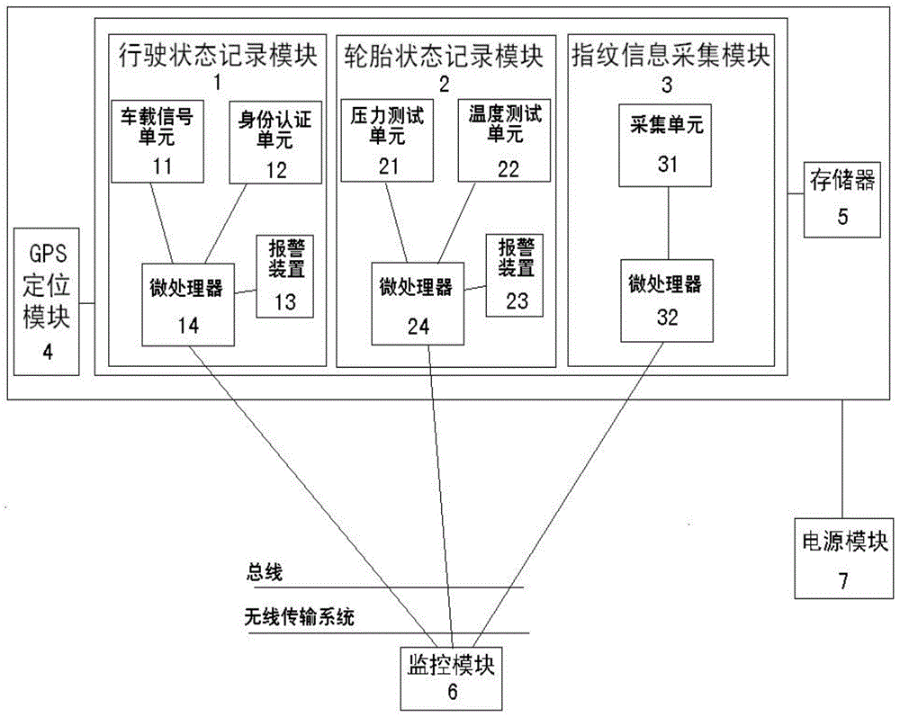
[0015] according to figure 1 As shown, a monitoring system for vehicle transportation safety includes a driving state recording module 1, a tire state recording module 2, a fingerprint information collection module 3, a GPS positioning module 4, a memory 5 and a monitoring module 6, and the driving state recording module 1 , tire state recording module 2, fingerprint information collection module 3, GPS positioning module 4 are all connected to power supply module 7; described driving state recording module 1, tire state recording module 2, fingerprint information collection module 3 are all connected to GPS positioning module 4 and memory 5; the driving state recording module 1 includes a vehicle signal unit 11, an identity authentication unit 12, and an alarm device 13, all of which are connected to a microprocessor 14; the tire state recording module 2 includes a pressure testing unit 21, a temperature testing unit 22, The alarm device 23 is all connected with the microprocessor 24; the fingerprint information acquisition module 3 includes an acquisition unit 31 and a microprocessor 32, both of which are connected; the data of the above microprocessors are all connected to the wireless transmission system through the data bus , the wireless transmission system uses the wireless network to send to the monitoring module 6.
[0016] In the application of the present invention, the vehicle-mounted signal unit 11 is provided with a vehicle speed sensor and an oil quantity sensor in the driving state recording module 1, and the pulse signal sent by the vehicle speed sensor is sampled and processed, and enters the microprocessor 14, and is counted regularly by software, and is calculated by the calculation. The measured speed, mileage and actual oil quantity can record the driver’s driving or violation behavior at the same time; the microprocessor 14 calculates the speed through the speed algorithm, and calculates the kilometer through the mileage algorithm, so as to carry out the speed, Recording, display, transmission of kilometers and actual fuel values. In addition, the microprocessor 14 is also connected with an identity authentication unit 12, and the driver uses an identity card to record the driver's identity through a contact IC machine. Driving state recording module 1 is also equipped with warning device 13, the pulse signal that the speed sensor on the car sends is sampled and processed, enters microprocessor 14, is counted regularly by software, calculates and obtains speed by speed algorithm, and speed and Compared with the highest threshold set by the machine, if it is higher than that, the driver will be prompted to overspeed and an alarm will sound.
[0017] The pressure test unit 21 and the temperature test unit 22 in the tire state recording module 2 are respectively connected to the microprocessor 24, and the microprocessor 24 is connected to the alarm device 23, and the sampled information is transmitted to the microprocessor by the pressure test unit 21 and the temperature test unit 22. device 24, after processing, when the index is exceeded, the alarm device 23 sends an alarm signal.
[0018] The output end of the acquisition unit 31 in the fingerprint information acquisition module 3 is connected to the microprocessor 32, and the acquisition unit 31 is provided with a fingerprint pressure-sensitive sensor, and the output end of the fingerprint pressure-sensitive sensor is connected to the fingerprint processing module, and the fingerprint information collected is passed through the microprocessor. Processor 32 has functions such as fingerprint entry, image processing, template storage, fingerprint comparison, fingerprint search and voice prompt.
[0019] The data of the above microprocessors are all connected to the wireless transmission system through the data bus, and the wireless transmission system sends it to the monitoring module 6 through the wireless network.
[0020] The power supply module 7 provides power for the operation of the entire system.
[0021] It should be understood that the examples are only for illustrating the present invention and are not intended to limit the scope of the present invention. In addition, it should be understood that after reading the content taught by the present invention, those skilled in the art can make various changes or modifications to the present invention, and these equivalent forms also fall within the scope of protection defined by the appended claims of the present application .

PUM

no PUM

Description & Claims & Application Information

We can also present the details of the Description, Claims and Application information to help users get a comprehensive understanding of the technical details of the patent, such as background art, summary of invention, brief description of drawings, description of embodiments, and other original content. On the other hand, users can also determine the specific scope of protection of the technology through the list of claims; as well as understand the changes in the life cycle of the technology with the presentation of the patent timeline. Login to view more.
Why Eureka
Try Eureka