Method for adjusting performance of electrically-small size bending line microstrip antenna

A technology of microstrip antenna and electrically small size, applied in the field of electronics, can solve the problems of limited range of performance parameters, limited space for adjustment, limited range of antenna performance, etc., and achieve the effect of good antenna performance indicators

Inactive Publication Date: 2015-04-29
FUJIAN UNIV OF TECH
3 Cites 0 Cited by

AI-Extracted Technical Summary

Problems solved by technology

[0012] For an electrically small-sized microstrip antenna, due to the limited space for adjustment, the range of size parameter changes is small, and the range of performanc...

Abstract

The invention discloses a method for adjusting performance of an electrically-small size bending line microstrip antenna. The method comprises the following steps that firstly, the area of an earth plate of the electrically-small size bending line microstrip antenna is determined as S; secondly, a metal sheet is inserted in a dielectric substrate, and the area of the metal sheet is S1; thirdly, the change range of the area S1 of the metal sheet is determined through the change trend of the performance of the antenna; fourthly, the optimal area S1 of the metal sheet is determined through an optimization method. The new method for adjusting the parameter of the performance of the antenna is provided. Antenna performance indexes better than the index of a bending line microstrip antenna in the prior art can be obtained.

Application Domain

Electrically short antennasAntenna details

Technology Topic

Dielectric substrateMicrostrip antenna +6

Image

  • Method for adjusting performance of electrically-small size bending line microstrip antenna

Examples

  • Experimental program(1)

Example Embodiment

[0031] In order to make the above objects, features and advantages of the present invention more clearly understood, the present invention will be described in further detail below with reference to the accompanying drawings and specific embodiments.
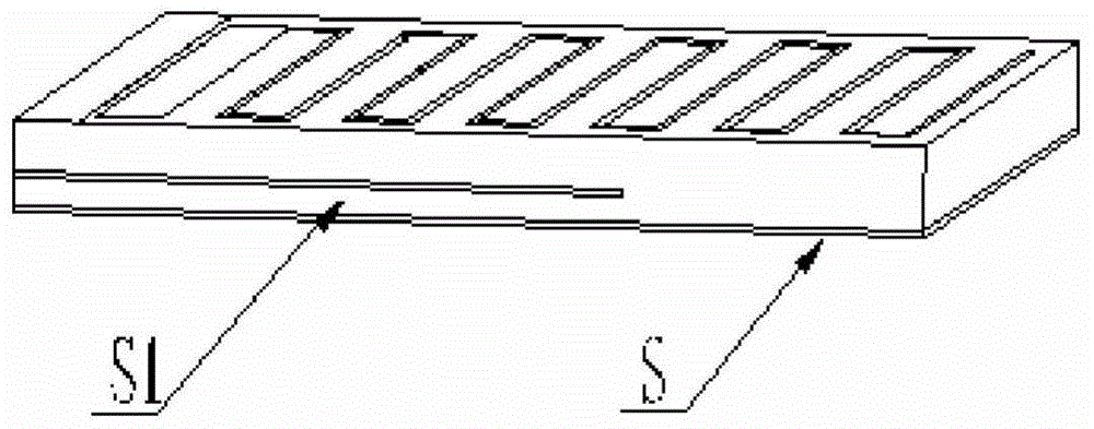
[0032] refer to figure 1 ,like figure 1 As shown, a method for adjusting the performance of an electrically small size meander line microstrip antenna includes the following steps:
[0033] Step 1) Determine the area of ​​the ground plate of the electrically small size meander line microstrip antenna as S, and the boundary conditions are:
[0034] e n ×E 1 = 0, on S;
[0035] e n ×H 1 =J S , on S;
[0036] Among them, the electric field in the dielectric substrate is E1, the magnetic field is H1, the surface current density on the ground plane is Js, e n is the normal unit vector of the interface.
[0037] Step 2) Insert a metal sheet inside the dielectric substrate. The area of ​​the metal sheet is S1. After adjustment, the boundary conditions have changed as follows:
[0038] e n ×E 1 = 0, on S;
[0039] e n ×H 1 =J S , on S;
[0040] e n ×E 1 = 0, on S1;
[0041] e n ×H 1 = 0, on S1;
[0042] Step 3) Determine the variation range of the metal sheet area S1 through the variation trend of the antenna performance;
[0043] Step 4) Determine the optimal metal sheet area S1 through the optimization method.
[0044] The three-dimensional electromagnetic simulation software HFSS of Ansoft can be used for calculation. The calculation process of the software is as follows
[0045] (1) Establish a structural model;
[0046] (2) Set boundary conditions, excitation conditions and solution conditions;
[0047] (3) Setting optimization conditions;
[0048] (4) Operational calculation;
[0049] (5) Calculation results.
[0050] For example: the size of a microstrip antenna is 23mm (width) × 46mm (length) × 2mm (thickness), and the relative dielectric constant of the medium is 4.84. According to the design of the traditional zigzag line microstrip antenna, the area of ​​the ground plate of the microstrip antenna is 23mm(W)×46mm(L), the center frequency is 0.97GHz;
[0051] According to the method of the present invention, the size of the metal sheet S1 is changed, and the length of the metal sheet S1 is changed under the condition of the same width, and the analysis results are as follows:
[0052] L1=3mm, f 0 =0.97GHz;
[0053] L1=13mm, f 0 =0.96GHz;
[0054] L1=23mm, f 0 =0.95GHz;
[0055] L1=33mm, f 0 =0.89GHz;
[0056] L1=43mm, f 0 =0.88GHz;
[0057] where f 0 Center frequency, L1 is the length of the metal sheet S1, changing the size of L1 can change the size of S1. When L1 is small, the center frequency is the same as that of the traditional meander-line microstrip antenna, which is in line with expectations: when L1 is small, the performance of the antenna is less affected.
[0058] Among them, to adjust the size of the metal sheet S1 of the electrically small size meandering line microstrip antenna, the size of the metal sheet S1 can be changed horizontally, or the size of the metal sheet S1 can be changed vertically, or the size of the metal sheet S1 can be changed at both ends of the horizontal direction, or the size of the metal sheet S1 can be changed at both ends of the vertical direction. The size of the metal sheet S1, or changing the size of the metal sheet S1 around it, can be achieved by one of the above methods, and other methods can also be used to change the boundary size. The central idea is to change the area of ​​the metal sheet S1 to achieve micro Performance tuning with antenna.
[0059] The descriptions of the above examples are only used to help understand the core idea of ​​the present invention; at the same time, for those skilled in the art, according to the idea of ​​the present invention, there will be changes in the specific implementation and application scope. , the contents of this specification should not be construed as limiting the invention.

PUM

no PUM

Description & Claims & Application Information

We can also present the details of the Description, Claims and Application information to help users get a comprehensive understanding of the technical details of the patent, such as background art, summary of invention, brief description of drawings, description of embodiments, and other original content. On the other hand, users can also determine the specific scope of protection of the technology through the list of claims; as well as understand the changes in the life cycle of the technology with the presentation of the patent timeline. Login to view more.
Why Eureka
Try Eureka