
Incoming and outgoing line module base

A technology for incoming and outgoing wires and incoming wires, applied in the directions of contact parts, electrical components, coupling devices, etc., can solve the problems of increasing installation volume and installation difficulty, increasing transfer busbars or wires, electric shock danger, etc., and achieving a compact and beautiful overall structure. , The effect of reducing the installation space and reducing the amount of installation

Active Publication Date: 2015-04-29
SHENZHEN ONTECH INTELLIGENT TECH CO LTD
View PDF4 Cites 11 Cited by
  • Summary
  • Abstract
  • Description
  • Claims
  • Application Information

AI Technical Summary

Problems solved by technology

[0005] The purpose of the present invention is to provide a module base for incoming and outgoing lines, which is used to overcome the problems in the prior art that the base of the incoming and outgoing line module needs to add transfer busbars or wires, resulting in increased installation volume and installation difficulty, and the risk of electric shock due to lack of protective functions. technical problem

Method used


Image

  • Incoming and outgoing line module base
  • Incoming and outgoing line module base
  • Incoming and outgoing line module base

Examples


Embodiment Construction

[0046] In order to make the technical problems to be solved, technical solutions and advantages of the present invention clearer, the present invention will be further described in detail below in conjunction with the accompanying drawings and embodiments. It should be understood that the specific embodiments described here are only used to explain the present invention, not to limit the present invention.

[0047] The implementation of the present invention will be described in detail below in conjunction with specific drawings.

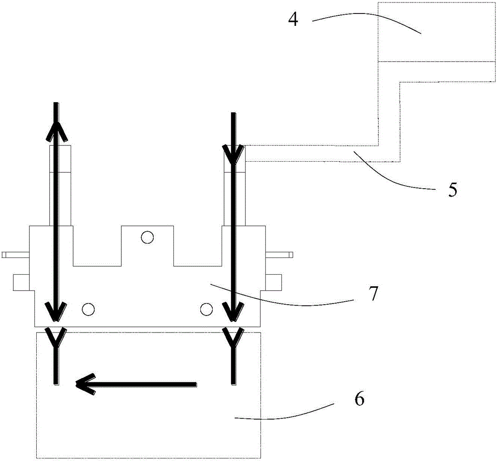
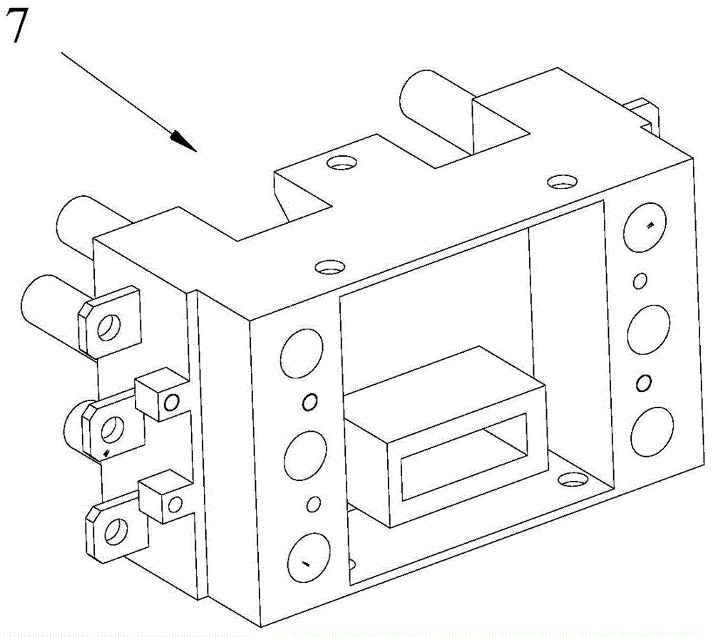
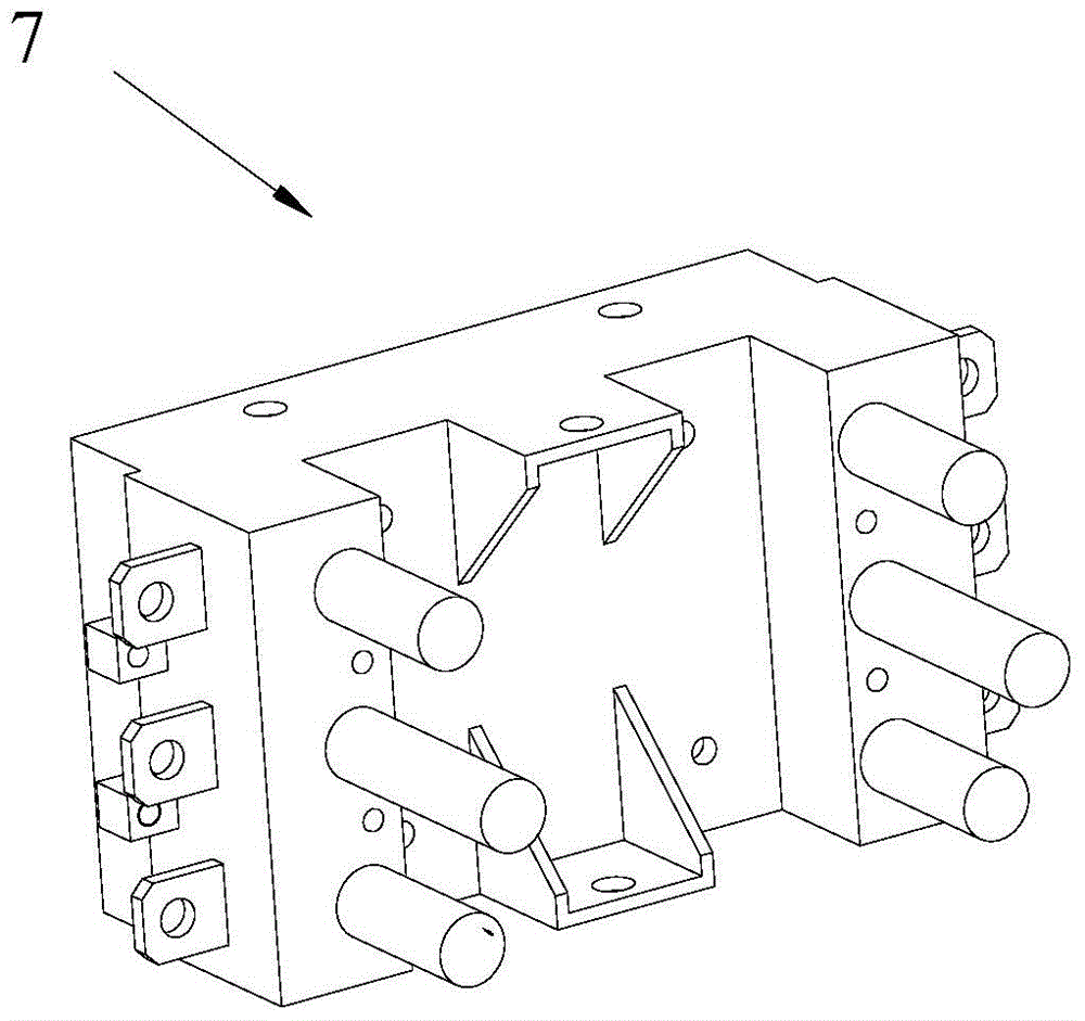
[0048] Such as Figure 5 ~ Figure 15 As shown, it is a base of an incoming and outgoing line module provided by a preferred embodiment of the present invention.

[0049] Such as Figure 5 ~ Figure 15 As shown, the base 0 of the incoming and outgoing line module includes an incoming line module 1 and an outgoing line module 2 located at the outgoing line end of the incoming line module 1. Obviously, the incoming line module 1 is mainly used to conn...


PUM


Abstract

The invention belongs to the technical field of power transmission and provides an incoming and outgoing line module base. The incoming and outgoing line module base comprises a plurality of first conductors externally connected with a load. A plurality of main shells which are stacked vertically and fixedly connected are arranged so as to form a general frame of the base, an inner cavity of each main shell is provided with a line incoming socketing end, a line outgoing socketing end, an input adapter component and an output adapter, one end of the input adapter component is connected with an input circuit externally, the other end of the input adapter component is connected with the line incoming socketing end, one end of the output adapter is connected with the corresponding first conductor, and the other end of the output adapter is connected with the line outgoing socketing end, accordingly, the input adapter (like adapter copper bar) and an external part of an external input circuit (like T-shaped screen) are arranged in the base so as to form an integral structure. Power transmission between the base and a vertical busbar is directly realized, the base is exquisite and attractive in appearance, mounting workload is greatly reduced, and mounting space is reduced.

Description

technical field [0001] The invention belongs to the technical field of electric power transmission and relates to a module base for incoming and outgoing lines. Background technique [0002] With the continuous development of power transmission technology, as well as the actual needs of various installations and maintenance, the power transmission method has changed from the simplest method that does not need to use the module base of the incoming and outgoing lines, but directly realizes the power transmission by the switch. It has gradually developed into the method of using the module base of the incoming and outgoing lines. Usually, this transmission method using the modular base of the incoming and outgoing lines is widely used in power systems, especially in substation AC systems, AC-DC integrated power systems, control cabinets, power distribution cabinets, and distribution cabinets. In the field of power distribution such as electric boxes, it mainly takes power from...

Claims


Application Information

Patent Timeline
Patent Type & Authority Applications(China)
IPC IPC(8): H01R13/02H01R13/502H01R13/66H01R13/447
CPCH01R13/02H01R13/447H01R13/502H01R13/6683
Inventor 吕刚罗德胜杨武
Owner SHENZHEN ONTECH INTELLIGENT TECH CO LTD
Learn More