
Support device

A technology of supporting devices and supporting legs, which is applied in the direction of electromechanical devices, electrical components, propulsion systems, etc., can solve problems such as the inability to adjust the height of the support, and achieve the effect of maintaining balance

Active Publication Date: 2017-02-01
江苏希太芯科技有限公司
View PDF4 Cites 0 Cited by
  • Summary
  • Abstract
  • Description
  • Claims
  • Application Information

AI Technical Summary

Problems solved by technology

[0003] In order to overcome the shortcomings of existing linear motor support devices that cannot adjust the height of the support, and when encountering uneven ground, the support for the support can only be realized by padding the ground, the present invention provides a support device

Method used


Image

  • Support device
  • Support device
  • Support device

Examples


Embodiment Construction

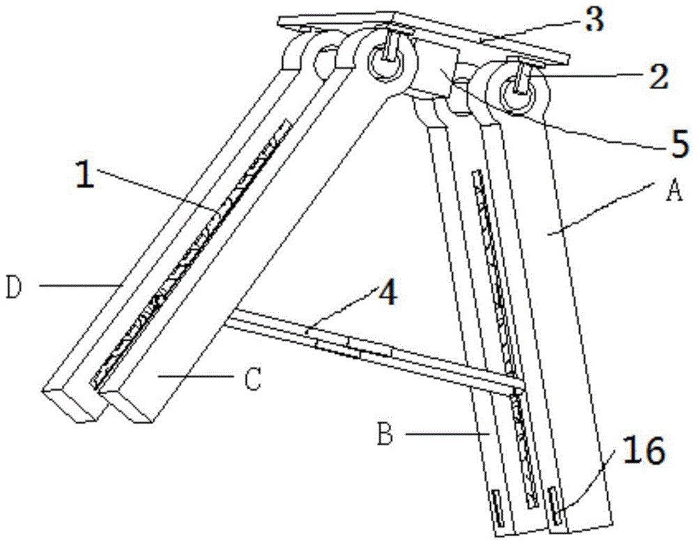
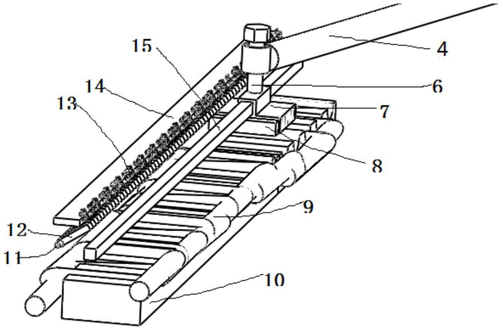
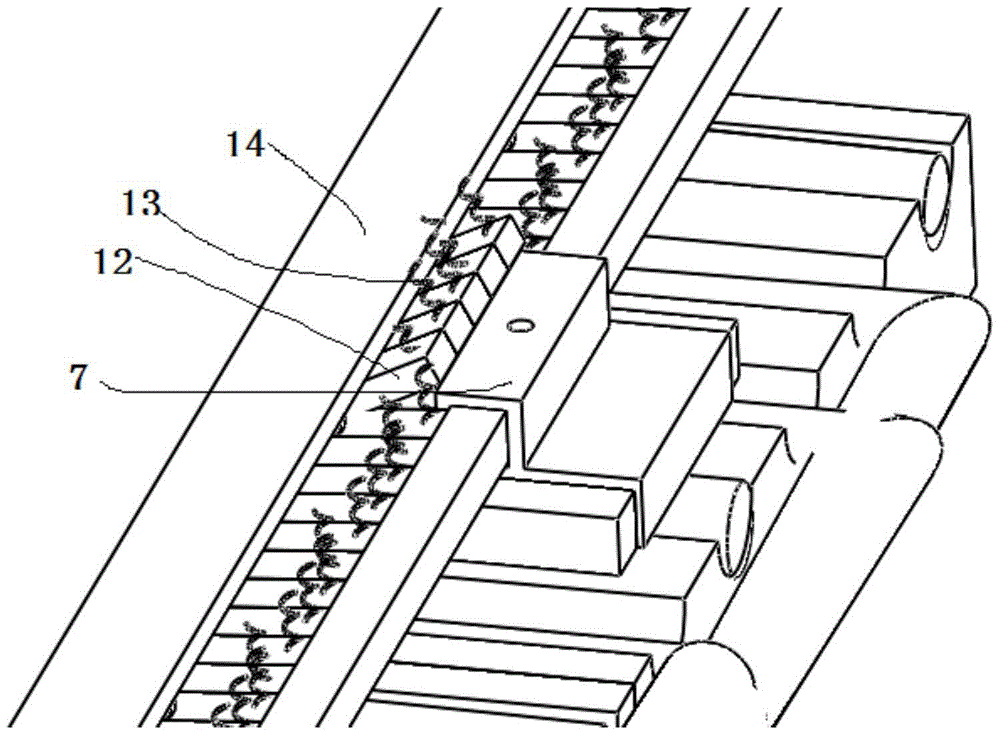
[0026] refer to Figure 1 to Figure 5 , a support device, including a support plate 3 and a first support leg A, a second support leg C, a third support leg B and a fourth support leg D distributed at the bottom of the support plate 3, the first support leg A and the fourth support leg The two support legs C and the third support leg B and the fourth support leg D are symmetrically arranged respectively, and also include a sliding rod 4, a power supply controller 5, the first support leg, the second support leg, the third support leg The supporting leg and the fourth supporting leg are respectively fixed on the bottom of the supporting plate 3 by the rolling shaft 2, and between the first supporting leg and the second supporting leg and between the third supporting leg and the fourth supporting leg The sliding rod 4 is provided, grooves 1 are respectively arranged on the opposite side of the first supporting leg to the second supporting leg and on the opposite side of the thir...


PUM


Abstract

The invention relates to a novel support device which comprises a support plate, a first support leg, a second support leg, a third support leg, a fourth support leg, sliding rods and a power supply controller, wherein the first support leg, the second support leg, the third support leg and the fourth support leg are distributed at the bottom of the support plate; the sliding rods are respectively arranged between the first support leg and the second support leg as well as between the third support leg and the fourth support leg; grooves are respectively formed in the opposite sides of the first support leg and the second support leg as well as in the opposite sides of the third support leg and the fourth support leg; the two ends of the sliding rods can slide along the length directions of the grooves; each groove is internally provided with a guide rail, a sliding block, an array type permanent magnet, a stator coil, a baffle and an electromagnetic coil capable of generating electromagnetic force after being electrified so as to absorb the baffles; the guide rails are arranged along the length directions of the grooves; the upper ends of the sliding blocks are connected with the sliding rods by rotating shafts; the power supply controller acts on the stator coil, so that the traction force for driving the sliding rods to slide is generated by the interaction between the array type permanent magnets and the stator coils.

Description

technical field [0001] The invention relates to a support device. Background technique [0002] The linear motor can be regarded as a rotary motor that is planed along the radial direction and straightened out. The side evolved from the stator is called the primary, and the side evolved from the rotor is called the secondary. Considering the actual situation, the primary and secondary are generally made into different lengths to ensure that the primary and secondary can be effectively coupled within the required travel range. For linear motors, the moving stage is generally called the mover, and the stationary stage is called the stator. Because the linear motor is driven by electromagnetic force, it can theoretically provide an infinite driving force. According to the characteristics of the linear motor drive, it can be applied in many occasions. The support devices of ordinary linear motors are all mechanical, and the height of the support cannot be adjusted. When encou...

Claims


Application Information

Patent Timeline
Patent Type & Authority Patents(China)
IPC IPC(8): H02K41/02
Inventor 杨亮亮许守金史伟民葛宏伟时军刘权庆
Owner 江苏希太芯科技有限公司
Learn More