Piezoelectric fan, radiator and electronic equipment

A piezoelectric fan and fan technology, which is applied in the construction of electrical equipment components, mechanical equipment, cooling/ventilation/heating transformation, etc., can solve the problems of unstable output airflow and low service life

Pending Publication Date: 2019-09-03
常州威图流体科技有限公司
View PDF2 Cites 8 Cited by
  • Summary
  • Abstract
  • Description
  • Claims
  • Application Information

AI Technical Summary

Problems solved by technology

[0006] In order to solve the technical problems of the piezoelectric fan in the prior art that the output air flow is unstable, the service life is too low, and only partial air circulation is realized, the present invention proposes a piezoelectric fan, which solves the above technical problems

Method used


Image

  • Piezoelectric fan, radiator and electronic equipment
  • Piezoelectric fan, radiator and electronic equipment
  • Piezoelectric fan, radiator and electronic equipment

Examples


Embodiment 1

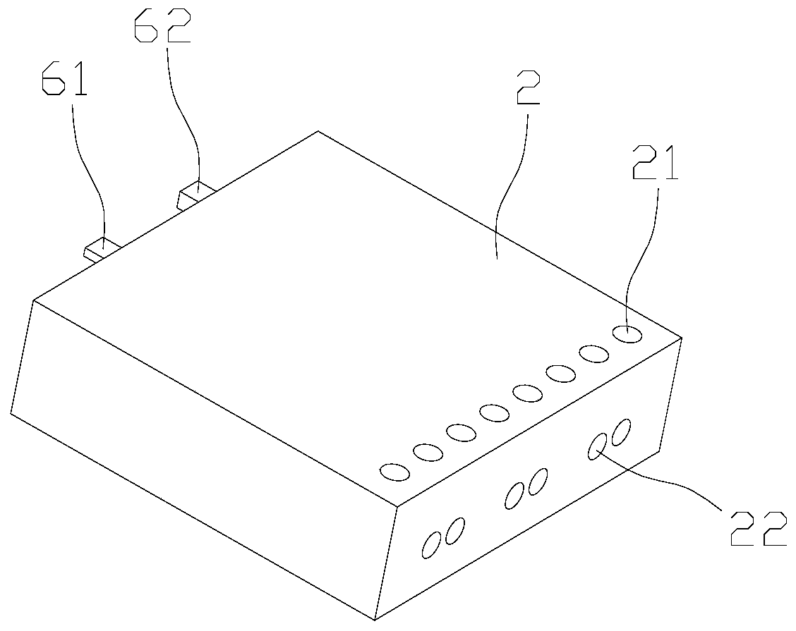
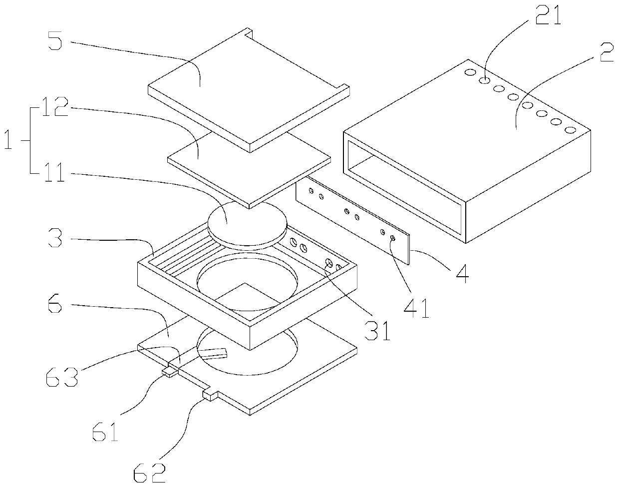
[0045] Such as Figure 1-9 As shown, this embodiment proposes a piezoelectric fan, which includes a fan body and a piezoelectric element 1. The piezoelectric element 1 is arranged inside the fan body. The piezoelectric element 1 deforms and squeezes fluid to be discharged from the fan body to achieve air flow. role.

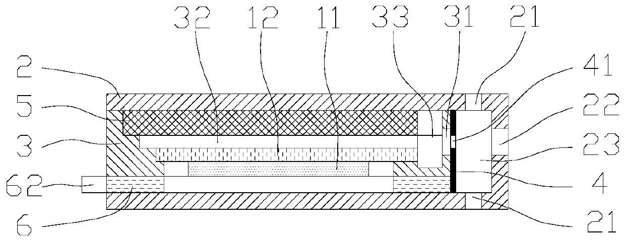
[0046] The fan body includes a casing 2 and a support 3 , the casing 2 is open at one end, and the support 3 can be inserted into the casing 2 from the opening of the casing 2 . The casing 2 is provided with an inlet 21 and an outlet 22 , and both the inlet 21 and the outlet 22 are arranged at an end of the casing 2 away from the opening. Specifically, the support member 3 is inserted into the housing 2, there is a gap between the outer end surface of the inner end of the support member 3 inserted into the housing 2 and the inner wall of the housing 2, and the inner end of the support member 3 and the inner wall of the housing 2 A jet cavity 23 is formed, the i...

Embodiment 2

[0075] Such as Figure 10 As shown, this embodiment is basically the same as Embodiment 1, the only difference is that there are two piezoelectric elements 1 and two electrode plates 6 in this embodiment, and no separator is required. Specifically, the two piezoelectric elements 1 are arranged symmetrically inside the support member 3 , the substrates 12 of the two piezoelectric elements 1 are arranged close to and spaced apart from each other, and a generating cavity 32 is formed between the two substrates 12 . The upper and lower ends of the supporting member 3 are provided with electrode plates 6, and the two electrode plates 6 are connected to the current for the two piezoelectric elements 1 respectively, and a buffer is formed between the ends of the two piezoelectric elements 1 and the inner wall of the supporting member 3 Cavity 33.

[0076] When the two piezoelectric elements 1 act on the generating chamber at the same time, the pumping force is enhanced, and the flow...


PUM


Abstract

The invention relates to the technical field of heat dissipation, in particular to a piezoelectric fan, a radiator and electronic equipment. The piezoelectric fan comprises a fan body and piezoelectric element, wherein an generating cavity and a flow spraying cavity are formed in the fan body, the generating cavity communicates with the flow spraying cavity through a flow spraying opening, a flowinlet and a flow outlet are formed in the fan body, and the flow inlet and the flow outlet communicate with the flow spraying cavity. The flow outlet is arranged corresponding to the flow spraying opening, and fluid discharged by the generating cavity forms a jet flow through the flow spraying opening, and the jet flow penetrates through the flow spraying cavity and is sprayed out of the fan bodythrough the flow outlet. The piezoelectric element is arranged in the fan body, and a piezoelectric element vibrates to change the volume of the generating cavity. According to the piezoelectric fan,the radiator and the electronic equipment, the technical problems of unstable output air flow, low service life, and mere local circulation of air in the prior art are solved.

Description

technical field [0001] The invention relates to the technical field of heat dissipation, in particular to a piezoelectric fan, a radiator and electronic equipment. Background technique [0002] In recent years, electronic equipment tends to be miniaturized, portable, and high-performance. Miniaturization increases the installation density of components inside electronic equipment. Portability requires electronic equipment to become thinner and thinner. High performance increases CPU frequency and heat. , electronic equipment faces the problem of insufficient heat dissipation space and a sharp increase in heating power. [0003] At present, most of the general-purpose electronic devices on the market use thermal radiation to dissipate heat. For example, graphene thermal radiation patches dissipate heat, and metal backplanes dissipate heat through radiation. Vulnerable to damage due to heat issues. [0004] The application with the patent number CN208047118U discloses a piez...

Claims


Application Information

Patent Timeline
Patent Type & Authority Applications(China)
IPC IPC(8): F04F5/16F04F5/44F04F5/46H05K7/20
CPCF04F5/16F04F5/44F04F5/46H05K7/20136
Inventor 吴垠周京京钟德坤张磊舒培
Owner 常州威图流体科技有限公司
Why Eureka
Try Eureka