Hydraulic ejection system for unmanned aerial vehicle

An unmanned aerial vehicle, hydraulic technology, applied in the direction of launch / tow transmission device, can solve the problems of poor maneuverability, harsh environmental requirements, low initial investment, etc., to achieve rapid buffer braking, compact pipeline layout, and stable overall performance Effect

Active Publication Date: 2016-04-13
郑州彩通科技有限公司
View PDF5 Cites 8 Cited by
  • Summary
  • Abstract
  • Description
  • Claims
  • Application Information

AI Technical Summary

Problems solved by technology

Among them, the rolling take-off launch equipment is simple and reliable, the acceleration overload is small, and the cost is low, but it is demanding on the environment and has poor maneuverability; electromagnetic ejection gas ejection has only been studied in a few developed countries, and there is no research in China; elastic ejection is only applicable to Light and small unmanned aerial vehicles; rocket-assisted launch occupies a small area, low initial investment, is less affected by the environment, and has better adaptability, but it involves the storage, transportation and use of explosives, which has great potential safety hazards and narrow application range; Hydraulic ejection has good safety and concealment, good economy, good adaptability, and can be used continuously for many times

Method used


Image

  • Hydraulic ejection system for unmanned aerial vehicle
  • Hydraulic ejection system for unmanned aerial vehicle

Examples


Embodiment Construction

[0033] The technical solutions in the embodiments of the present invention will be clearly and completely described below in conjunction with the accompanying drawings in the present invention. Apparently, the described embodiments are only illustrative partial implementations of the present invention, and are not intended to limit the scope of the present invention. , any equivalent changes and modifications made by those skilled in the art without departing from the concepts and principles of the present invention shall fall within the protection scope of the present invention.

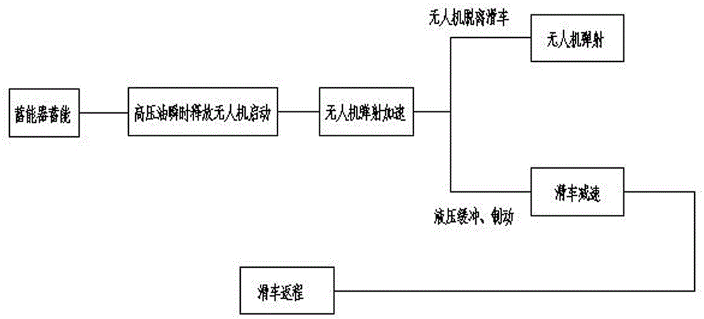
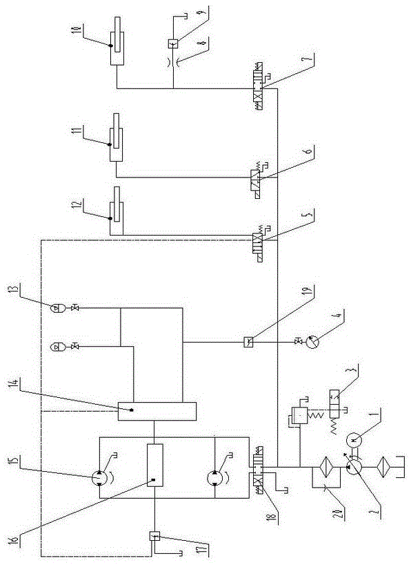
[0034] see figure 1 , in the figure, the UAV hydraulic ejection system of the present invention includes a hydraulic drive part, a hydraulic energy storage part, a hydraulic start part, a hydraulic buffer part, a hydraulic brake part, a hydraulic oil tank, and a hydraulic pipeline for connection between each part Wherein, the hydraulic drive part includes a motor 1, a variable pump 2 and a hydraulic...


PUM


Abstract

The invention relates to a hydraulic ejection system for an unmanned aerial vehicle. The hydraulic ejection system comprises a hydraulic driving part, a hydraulic energy storage part, a hydraulic starting part, a hydraulic buffering part, a hydraulic brake part, a hydraulic oil tank and a hydraulic pipeline for being connected between the hydraulic drive part, the hydraulic energy storage part, the hydraulic starting part, the hydraulic buffering part, the hydraulic braking part and the hydraulic oil tank, wherein the hydraulic driving part comprises a motor, a variable capacity pump, hydraulic motors and an electro-hydraulic directional control valve 18; the energy storage part comprises energy accumulators, an electromagnetic relief valve and a pressure gage; the hydraulic starting part comprises a starting hydraulic cylinder and an electro-hydraulic directional control valve 6; the hydraulic cushioning part comprises a cushioning hydraulic cylinder and an electro-hydraulic directional control valve 7; the hydraulic braking part comprises a braking hydraulic cylinder and an electro-hydraulic directional control valve 5; the energy accumulators are connected with the hydraulic motors in series, and besides, a control valve group is connected to the hydraulic pipeline between the energy accumulators and the hydraulic motors in series; besides, a brake valve group and a prefill valve are arranged on the hydraulic motors; besides, the control valve group is connected with the brake valve group. The hydraulic ejection system disclosed by the invention is high in drive force, rapid in cushioning and braking, stable and reliable in properties, and adaptive to operating requirements for different take-off weights and different take-off speeds of different unmanned aerial vehicles.

Description

technical field [0001] The invention belongs to the technical field of unmanned aerial vehicles, in particular to a hydraulic ejection system for unmanned aerial vehicles. Background technique [0002] Unmanned aircraft, referred to as unmanned aerial vehicle, is an unmanned aircraft controlled by radio remote control equipment and its own program control device. Because of its small size, low cost, easy to use, low requirements on the combat environment, and strong battlefield survivability, it is favored by armies all over the world and is widely used in the military field. In addition, countries around the world are actively expanding the application scope of civilian drones. The technical and economic effects of using drones in fields such as electric power, communications, meteorology, agriculture, forestry, ocean, and exploration are very promising. [0003] With the wide application of UAVs in various fields of society, the supporting launching devices have also been...

Claims


Application Information

Patent Timeline
Patent Type & Authority Applications(China)
IPC IPC(8): B64F1/06
CPCB64F1/06
Inventor 梁大伟马胜钢
Owner 郑州彩通科技有限公司
Why Eureka
Try Eureka