Silicon-controlled trigger signal generating device

A technology for triggering signals and generating devices, applied in electrical components, pulse technology, electronic switches, etc., can solve problems such as complex circuit pages, and achieve the effects of simple debugging, stable triggering, and good linearity

Inactive Publication Date: 2015-04-29
XIAN ZAOXIN ELECTRONICS INFORMATION TECH
View PDF0 Cites 0 Cited by
  • Summary
  • Abstract
  • Description
  • Claims
  • Application Information

AI Technical Summary

Problems solved by technology

[0002] The linear difference between the phase shift and the control DC voltage in the commonly used thyristor trigger circuit, the circuit page is more complicated

Method used


Image

  • Silicon-controlled trigger signal generating device
  • Silicon-controlled trigger signal generating device
  • Silicon-controlled trigger signal generating device

Examples


Embodiment Construction

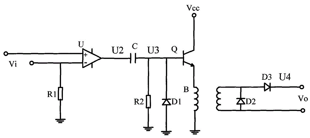
[0012] Below in conjunction with accompanying drawing, the technical scheme of invention is described in detail:

[0013] Such as figure 1 As shown, the thyristor trigger signal generating device is characterized in that it includes an operational amplifier, a capacitor, a triode, a transformer, three diodes and two resistors, wherein the positive and negative input terminals of the operational amplifier are connected to the input voltage, and the reverse input terminals of the operational amplifier are connected to the input voltage. The input terminal is connected in series with the first resistor and grounded, the output terminal of the operational amplifier is connected in series with a capacitor, and then respectively connected to one end of the second resistor, the cathode of the first diode and the base of the triode, and the other end of the second resistor to the first two The anodes of the pole tubes are grounded respectively, the collectors of the triodes are connec...


PUM


Abstract

The invention discloses a silicon-controlled trigger signal generating device. The silicon-controlled trigger signal generating device comprises an operational amplifier, a capacitor, a triode, a transformer, three diodes and two resistors. The silicon-controlled trigger signal generating device is simple in debugging, stable in triggering and good in linearity.

Description

technical field [0001] The invention relates to a thyristor trigger signal generating device, which belongs to the technical field of thyristor trigger. Background technique [0002] The linear difference between the phase shift and the control DC voltage in the commonly used thyristor trigger circuit, the circuit page is more complicated. Contents of the invention [0003] The object of the present invention is to provide a thyristor trigger signal generating device aiming at the defects existing in the prior art. [0004] In order to achieve the above object, the present invention adopts the following technical solutions: [0005] The thyristor trigger signal generating device of the present invention is characterized in that it comprises an operational amplifier, a capacitor, a triode, a transformer, three diodes and two resistors, wherein the positive and negative input terminals of the operational amplifier are connected to the input voltage, and the reverse input of...

Claims


Application Information

Patent Timeline
Patent Type & Authority Applications(China)
IPC IPC(8): H03K17/72
Inventor 不公告发明人
Owner XIAN ZAOXIN ELECTRONICS INFORMATION TECH
Why Eureka
Try Eureka