Method and device for determining forwarding path in shortest path bridge network

A shortest path bridging and forwarding path technology, applied in data switching network, hybrid switching system, digital transmission system, etc., can solve problems such as unreachable load sharing and unsatisfactory load sharing effect

Active Publication Date: 2015-04-29
NEW H3C TECH CO LTD
View PDF3 Cites 6 Cited by
  • Summary
  • Abstract
  • Description
  • Claims
  • Application Information

AI Technical Summary

Problems solved by technology

Limited by the design of some switch chips, the effect of load sharing is not ideal when the number of flows is small, and the effect of load sharing may not be achieved in some cases

Method used


Image

  • Method and device for determining forwarding path in shortest path bridge network
  • Method and device for determining forwarding path in shortest path bridge network
  • Method and device for determining forwarding path in shortest path bridge network

Examples


Embodiment Construction

[0053] The present invention will be further described in detail below in conjunction with the accompanying drawings and specific embodiments.

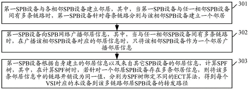
[0054] image 3 A flowchart of a method for determining a forwarding path in an SPB network provided by an embodiment of the present invention, as shown in image 3 As shown, the specific steps are as follows:

[0055] Step 301: The first SPB device establishes neighbors with each adjacent SPB device, wherein, when there are multiple links between the first SPB device and any adjacent SPB device, the first SPB device separately communicates with the Neighboring SPB devices establish a neighbor.

[0056] Wherein, for example: when there are multiple links between the first SPB device and the adjacent second SPB device, establishing a neighbor with the second SPB device for each link includes:

[0057] The first SPB device sends Hello messages to each link between the second SPB device, wherein the local node IDs carried in the Hello...


PUM


Abstract

A method is described in which a first shortest path bridging (SPB) node and a neighboring second SPB node are connected via n links; a plurality of different neighborhoods are established between the first node and the second SPB node; and a shortest path first (SPF) tree is calculated in accordance with the links with the same cost.

Description

technical field [0001] The present invention relates to the technical field of shortest path bridging (SPB, Shortest Path Bridging), in particular to a method and device for determining a forwarding path in an SPB network. Background technique [0002] SPB is created to solve some disadvantages of Multiple Spanning Tree Protocol (MSTP, Multiple Spanning Tree Protocol) networking in large-scale networking. Compared with MSTP networking, it has the following advantages: the software layer controls the forwarding of specific traffic by issuing driving rules, and does not need to completely block the link to cause resource waste; calculate the optimal forwarding based on link status and overhead path, minimizing delay and unnecessary bandwidth consumption; providing load balancing for different services, making full use of redundant links in the network, etc. [0003] The principle of SPB is as follows: [0004] 1. After two nodes are connected through a direct line or a pure ...

Claims


Application Information

Patent Timeline
Patent Type & Authority Applications(China)
IPC IPC(8): H04L12/803H04L12/721H04L12/753H04L45/02
CPCH04L12/6418H04L45/026H04L45/124
Inventor 黄智明
Owner NEW H3C TECH CO LTD
Why Eureka
Try Eureka