
Method for maximizing sequential output in a disk array storage device

Inactive Publication Date: 2001-02-13
EMC IP HLDG CO LLC
View PDF12 Cites 76 Cited by
  • Summary
  • Abstract
  • Description
  • Claims
  • Application Information

AI Technical Summary

Benefits of technology

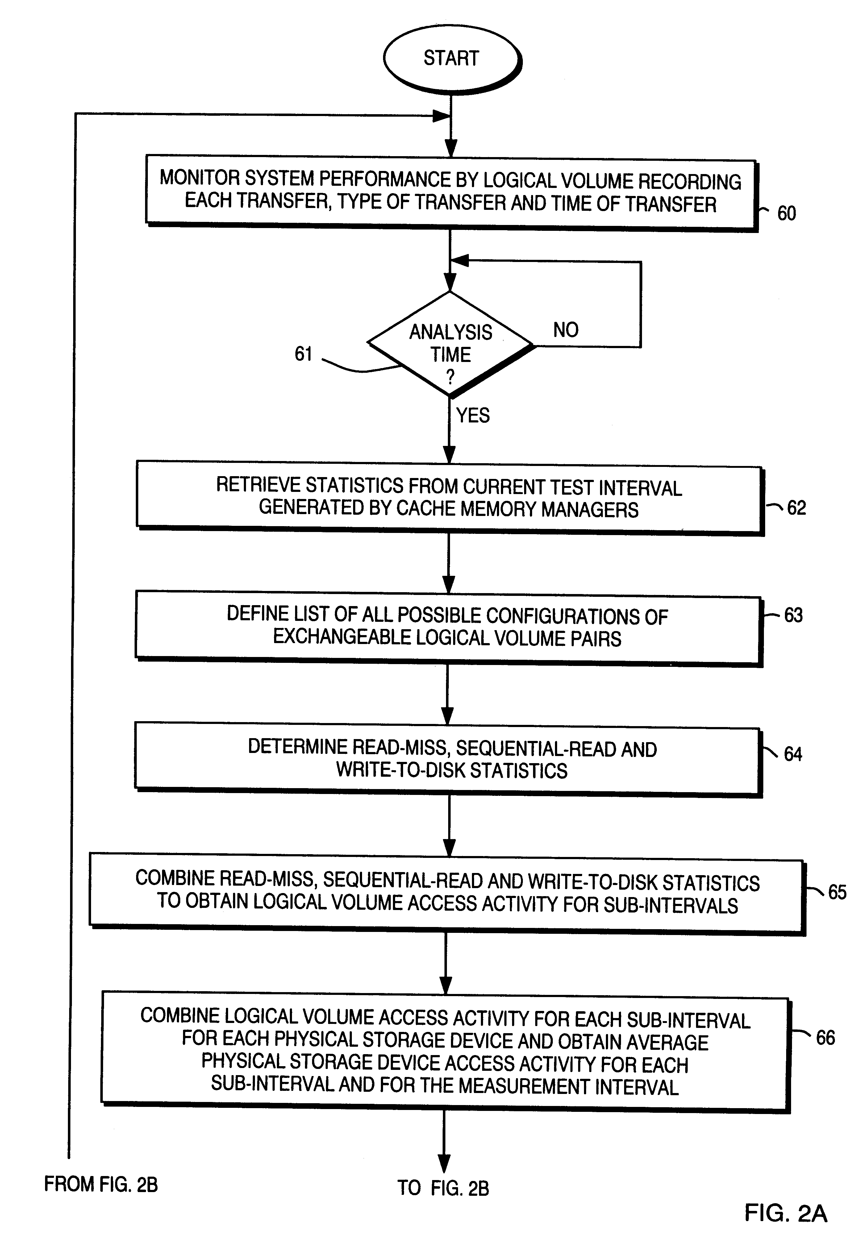
In accordance with this invention, the load on a plurality of physical disk storage devices can be balanced by exchanging data blocks on two physical disk storage devices that are divided into blocks of contiguous storage locations. A list of all pairs of exchangeable data blocks on the physical disk storage devices is prepared. Disk utilization statistics are compiled for each data block in each physical disk storage device over a time interval. A configuration of with a pair of data blocks on different physical disk storage devices is implemented if an analysis determines that the exchange will improve physical disk storage device operations.

Problems solved by technology

The management of such resources becomes very important because the ineffective utilization of the capabilities of such an array can affect overall data processing system performance significantly.
Often times allocations based upon this limited information are or become inappropriate.
When this occurs, the original configuration can degrade overall data processing system performance dramatically.
None of these systems suggests the implementation of load balancing by the dynamic reallocation or configuration of existing data sets within the disk array storage system.
However, if the physical drives have multiple logical volumes, sub-volumes or other forms of blocks of contiguous storage locations, the net effect may not balance the load with respect to the totality of the physical disk drives.
Thus, none of the foregoing references discloses or suggests a method for providing a dynamic reallocation of physical address space based upon actual usage.

Method used


Image

  • Method for maximizing sequential output in a disk array storage device
  • Method for maximizing sequential output in a disk array storage device
  • Method for maximizing sequential output in a disk array storage device

Examples


Embodiment Construction

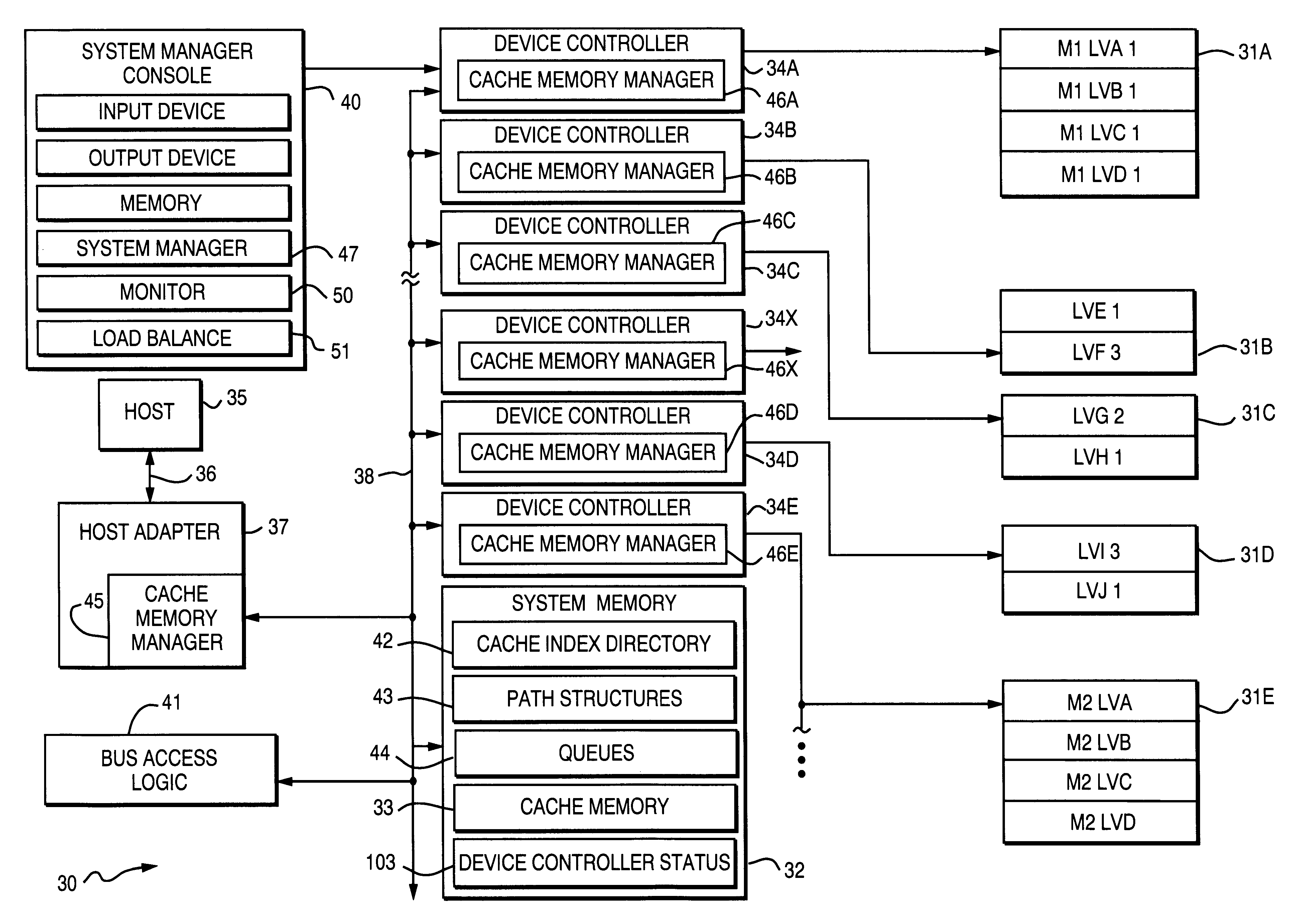
FIG. 1 depicts, in block form, and as a typical data processing system 30, a Symmetrix 5500 series integrated cached disk array that includes such a data memory system with a number of data storage devices or physical disk storage devices 31A, 31B, 31C, 31D and 31E, by way of example, and a system memory 32 with a cache memory 33. In this particular embodiment the system 30 includes several device controllers 34A, 34B, 34C, 34D and 34E connected to corresponding ones of the physical disk storage devices 31A through 31E plus a device controller 34X representing other controllers and attached physical disk storage devices. Each device controller may have a known basic structure or a more sophisticated structure associated with mirrored operations as described in the above-identified U.S. Pat. No. 5,819,310.

The device controller 34A is shown with an associated physical disk storage device 31A divided into the mirrored logical volumes M1-LVA, M1-LVB, M1-LVC and M1-LVD; the device contro...


PUM


Abstract

Load balancing of activities on physical disk storage devices is accomplished by monitoring reading and writing operations to blocks of contiguous storage locations on the physical disk storage devices. A list of exchangeable pairs of blocks is developed based on size and function. Statistics accumulated over an interval are then used to obtain access activity values for each block and each physical disk drive. A statistical analysis leads to a selection of one block pair. After testing to determine any adverse effect of making that change, the exchange is made to more evenly distribute the loading on individual physical disk storage devices.

Description

1. Field of the InventionThis invention generally relates to the management of resources in a data processing system and more particularly to the management of a disk array storage device.2. Description of Related ArtMany data processing systems now incorporate disk array storage devices. Each of these devices comprises a plurality of physical disks arranged into logical volumes. Data on these devices is accessible through various control input / output programs in response to commands, particularly reading and writing commands from one or more host processors. A Symmetrix 5500 series integrated cached disk array that is commercially available from the assignee of this invention is one example of such a disk array storage device. This particular array comprises multiple physical disk storage devices or drives with the capability of storing large amounts of data up to one terabyte or more. The management of such resources becomes very important because the ineffective utilization of th...

Claims


Application Information

Patent Timeline
IPC IPC(8): G06F11/34G11B17/22G06F3/06G06F12/00
CPCG06F3/061G06F3/0634G06F3/0653G06F3/0689G06F11/3433G06F11/3447G06F11/3485G11B17/22G06F11/3409G06F11/3419G06F2201/885G06F11/3452
Inventor BACHMAT, EITAN
Owner EMC IP HLDG CO LLC
Learn More