Upper frame of multi-cylinder cone crusher

A technology of cone crusher and top frame, which is applied in the field of mining equipment, can solve the problems of strong vibration of the top frame, affect the service life, and easily generate cracks, etc., and achieve the effects of precise size adjustment, prolonging the service life and reducing vibration

Active Publication Date: 2015-05-06
ZHEJIANG ZHEKUANG HEAVY IND CO LTD
View PDF7 Cites 0 Cited by
  • Summary
  • Abstract
  • Description
  • Claims
  • Application Information

AI Technical Summary

Problems solved by technology

However, the top frame of the existing cone crusher has the following two disadvantages: 1. The top frame of the existing cone crusher can only be used for feeding, and the axial height of the fixed cone cannot be adjusted; therefore, in order to adjust the crushing The size of the cavity is used to crush stones of different sizes. The existing cone crusher is also equipped with a hydraulic lifting mechanism for changing the axial height of the movable cone group; but under the hydraulic lifting mechanism, the control accuracy of the size of the crushing cavity of the cone crusher Not high, and the maintenance cost of the large hydraulic lifting mechanism is too high; 2. The top frame structure of the existing cone crusher is single, and the fixed cone liner and the top frame are rigidly connected. During the process of crushing stones, the cone crusher will produce Huge load, rigidly connected fixed cone liner will cause strong vibration of the top frame, and the top frame is prone to cracks after long-term vibration and stone collision, which seriously affects its service life

Method used


Image

  • Upper frame of multi-cylinder cone crusher
  • Upper frame of multi-cylinder cone crusher
  • Upper frame of multi-cylinder cone crusher

Examples


Embodiment Construction

[0018] The preferred embodiments of the present invention will be described in further detail below in conjunction with the accompanying drawings.

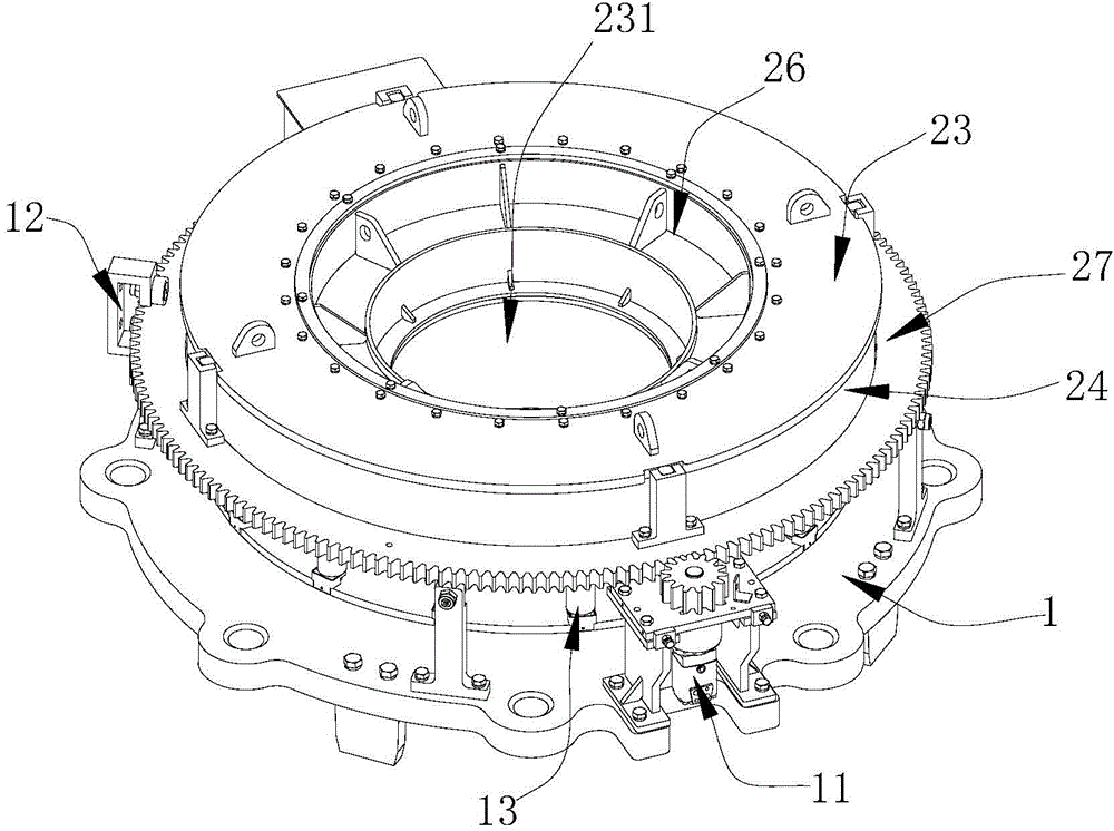
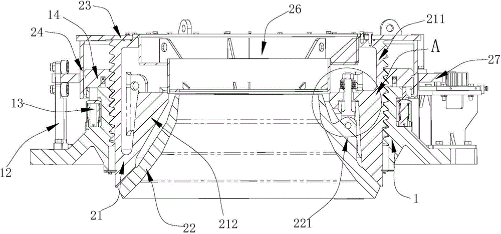
[0019] Such as Figure 1 ~ Figure 4 The top frame of a multi-cylinder cone crusher shown includes a connecting frame 1 and a fixed cone frame.

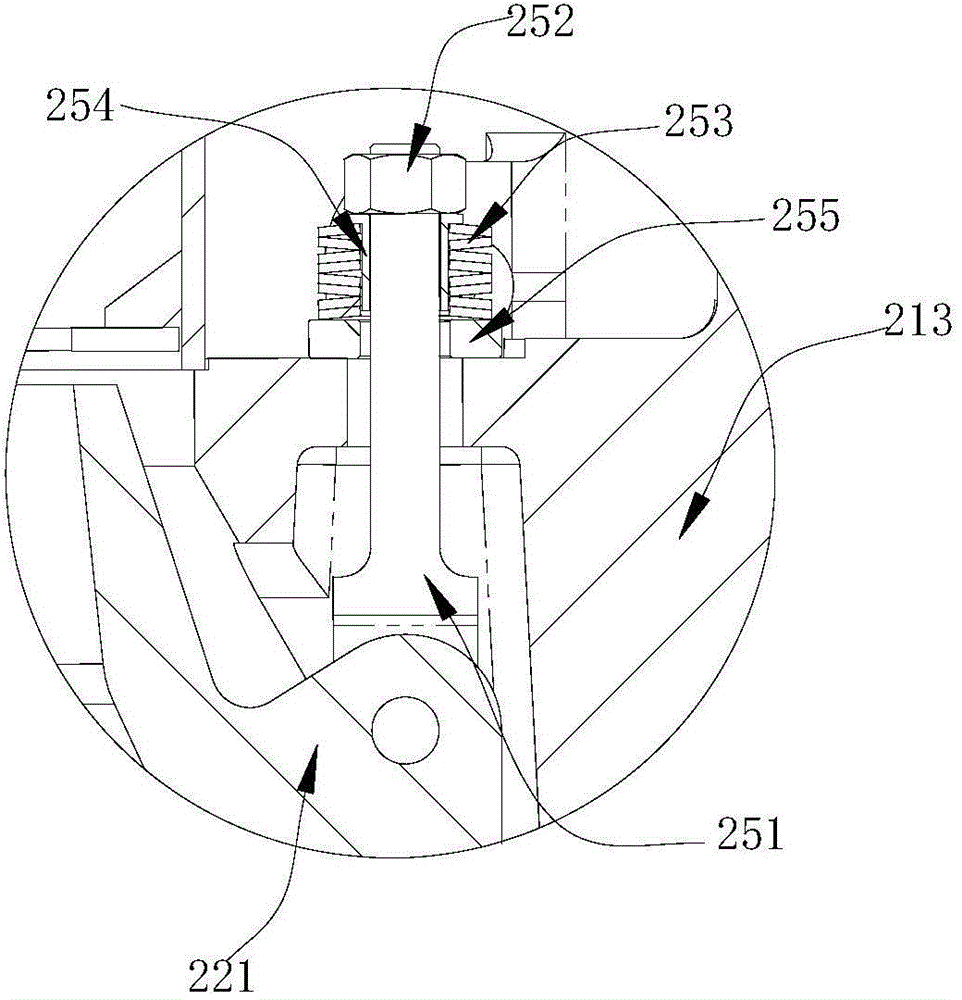
[0020] The fixed cone frame includes a fixed cone body 21 , a fixed cone liner 22 , a fixed cone drive top plate 23 and a fixed cone drive side plate 24 . The fixed cone 21 includes a fixed cone adjusting ring 211 on the outside, a fixed cone fixing sleeve 212 inside the fixed cone adjusting ring 211, and multiple sets of fixed cone connections for connecting the fixed cone fixing sleeve 212 and the fixed cone adjusting ring 211 Seat 213 and multiple fixed cone reinforcing ribs 214. The lower end of the fixed cone fixing sleeve 212 is integrally connected with the lower end of the fixed cone adjusting ring 211. Multiple sets of fixed cone connecting seats 213 and a plurality of fixed co...


PUM


Abstract

The invention relates to the field of mine equipment. An upper frame of a multi-cylinder cone crusher comprises a connecting frame and a fixed cone frame, wherein the fixed cone frame comprises a fixed cone body, a fixed cone lining plate, a fixed cone driving top plate and a fixed cone driving side plate, wherein the fixed cone lining plate is installed in the fixed cone body in a positioning manner; the outer side wall surface of the fixed cone lining plate is also provided with a fixed cone pin boss which is integrally connected with the outer side wall surface; the fixed cone pin boss is flexibly connected with and fixed on the fixed cone body via a fixed cone connecting structure; the outer side wall surface of the fixed cone body is in threaded connection with the inner side wall surface of the connecting frame; the outer side surface of the fixed cone driving side plate is provided with a driving ring large gear ring; the driving ring large gear ring and the fixed cone driving side plate are in peripheral positioning, and are not in axial positioning; the connecting frame is provided with a regulating motor and a large gear ring support base which connected in a drive mode; the large gear ring support base is used for axially positioning the driving ring large gear ring. The upper frame of the cone crusher can adjust the axial height of the fixed cone so as to change the size of the crushing cavity, and also has a shock absorption effect, so that the service life is prolonged.

Description

technical field [0001] The invention relates to the field of mining equipment, in particular to a top frame of a multi-cylinder cone crusher. Background technique [0002] The multi-cylinder cone crusher is a kind of mining machinery used for crushing stones. Its principle is to crush stones through the mutual cooperation between the moving cone and the fixed cone that rotates through the swing; between the moving cone and the fixed cone is the cone crusher. crushing cavity. The existing cone crusher includes a frame, and a transmission mechanism, an eccentric mechanism and a moving cone group installed inside the frame. The frame is divided into a bottom frame and a top frame. The top frame is mainly used for feeding and installing the fixed cone liner. However, the top frame of the existing cone crusher has the following two disadvantages: 1. The top frame of the existing cone crusher can only be used for feeding, and the axial height of the fixed cone cannot be adjusted...

Claims


Application Information

Patent Timeline
Patent Type & Authority Applications(China)
IPC IPC(8): B02C2/02
Inventor 陈利华陈连方赵孟军李国强陈炳敏
Owner ZHEJIANG ZHEKUANG HEAVY IND CO LTD
Why Eureka
Try Eureka