
Assembling tool for valve locking block

A valve lock and block assembly technology, used in metal processing, manufacturing tools, metal processing equipment and other directions, can solve the problems of low assembly success rate, difficulty in pressing in place at one time, difficulty, etc., to reduce labor intensity and improve production. Efficiency and product assembly quality, the effect of reducing force

Active Publication Date: 2015-05-06
CHONGQING SOKON IND GRP CO LTD
View PDF6 Cites 9 Cited by
  • Summary
  • Abstract
  • Description
  • Claims
  • Application Information

AI Technical Summary

Problems solved by technology

[0002] The assembly of the engine valve lock block on the automatic equipment is unqualified and needs to be repaired separately or during the assembly process of a single product, use the traditional palm to press the tooling, after the spring seat and the lock block are assembled, put it on the valve spring, and then place the tooling On the spring seat, slowly press the head of the pressure rod with the palm of your hand, so that the spring seat moves down, and the lock block falls into the lock clip groove of the valve. This method needs to overcome the spring force of the valve. , it is difficult for the lock block to fall into the valve lock clip groove, and it is difficult for one person to press and fit it in place at one time, and the success rate of assembly is very low

Method used


Image

  • Assembling tool for valve locking block
  • Assembling tool for valve locking block
  • Assembling tool for valve locking block

Examples


Embodiment Construction

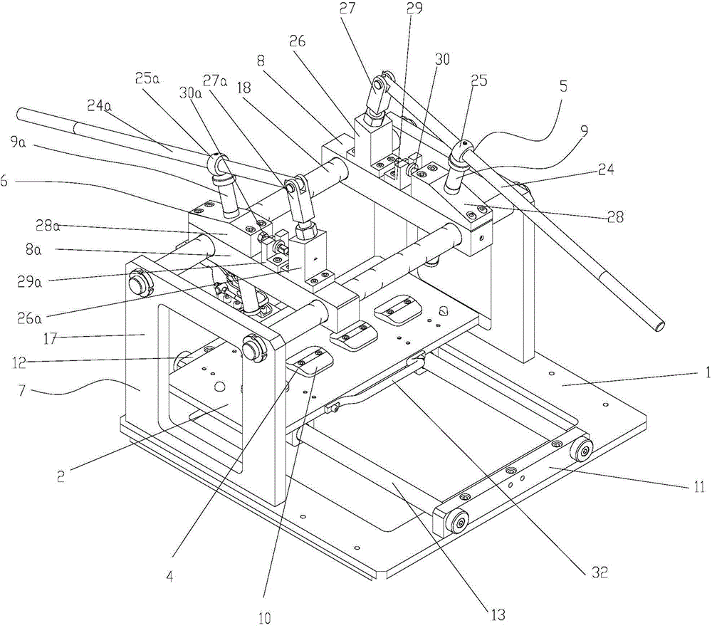
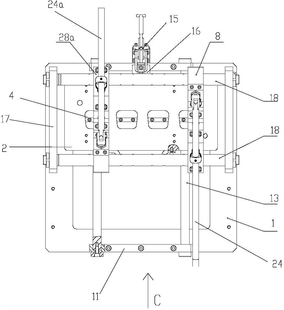
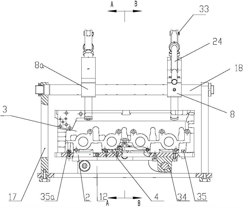
[0023] As shown in the figure: the valve lock block assembly tooling of this embodiment includes a base plate 1, a workpiece positioning support plate 2 and a valve lock block press-fit assembly, and the workpiece positioning support plate 2 is provided with a The chamber forms a cushion block 4 for adaptive support, and the valve press-fit assembly includes a support frame and an exhaust valve lock block press-fit assembly 5 and an intake valve lock block press-fit assembly 6 fixedly arranged on the support frame. The support frame 7 is fixedly arranged on the base plate 1, and the press-fit assembly 5 of the exhaust valve lock block has the same structure as the press-fit assembly of the intake side valve, and both include a base slider (base slider 8 in the figure). and base slide block 8a), pressure head assembly (in the figure, pressure head assembly 9 and pressure head assembly 9a) and a lever drive mechanism for driving the pressure head assembly to press-fit the lock bl...


PUM


Abstract

The invention discloses an assembling tool for a valve locking block. The assembling tool comprises a bottom plate, a workpiece locating and supporting plate and a valve locking block press-fit assembly, and a cushion block is arranged on the workpiece locating and supporting plate. A valve press-fit assembly comprises a supporting frame, an exhaust valve locking block press-fit assembly and an intake valve locking block press-fit assembly, wherein the exhaust valve locking block press-fit assembly and the intake valve locking block press-fit assembly are fixedly arranged on the supporting frame. The exhaust valve locking block press-fit assembly and the intake valve locking block press-fit assembly are of the same structure and both comprise base sliding blocks, pressure head components and lever drive mechanisms. The pressure head components are in relative sliding fit with the base sliding blocks in the manner of being identical with valves on the corresponding side of an engine cylinder head on the aspect of an inclination degree. Pressure heads are identical with the valves on the corresponding side on the aspect of the inclination angle, so the tool can be prevented from interfering with other components and damaging the components due to pressing. In addition, the valves are jacked through a bottom cushion block arranged on the bottom plate, valve rods will not move, shake is avoided, the press-fit stability is guaranteed, and therefore the press-fit effect can be guaranteed.

Description

technical field [0001] The invention relates to the field of tooling, in particular to a valve lock block assembly tooling. Background technique [0002] The assembly of the engine valve lock block on the automatic equipment is unqualified and needs to be repaired separately or during the assembly process of a single product, use the traditional palm to press the tooling, after the spring seat and the lock block are assembled, put it on the valve spring, and then place the tooling On the spring seat, slowly press the head of the pressure rod with the palm of your hand, so that the spring seat moves down, and the lock block falls into the lock clip groove of the valve. This method needs to overcome the spring force of the valve. , It is difficult for the lock block to fall into the valve lock clip groove, and it is difficult for one person to press and fit it in place at one time, and the success rate of assembly is very low. [0003] Therefore, it is necessary to improve th...

Claims


Application Information

Patent Timeline
Patent Type & Authority Applications(China)
IPC IPC(8): B25B27/02
CPCB23P19/006B23P19/02
Inventor 张兴海段伟李建青王艳朋李建斌高付兵
Owner CHONGQING SOKON IND GRP CO LTD
Learn More