Manual exhaust auxiliary device for hydraulic braking system

A technology of hydraulic braking and auxiliary devices, applied in the directions of brakes, brake components, transportation and packaging, etc., can solve problems such as inability to empty, waste of brake fluid, time-consuming and labor-intensive efficiency, meet safety requirements and improve economic benefits. , the effect of saving manpower

Active Publication Date: 2015-05-06
ANHUI JIANGHUAI AUTOMOBILE GRP CORP LTD
View PDF5 Cites 2 Cited by
  • Summary
  • Abstract
  • Description
  • Claims
  • Application Information

AI Technical Summary

Problems solved by technology

[0005] During the exhaust process, there must always be one person stepping on the brake pedal repeatedly on the driver's seat, one person must continuously tighten and tighten the bleed screw at the end of the wheel cylinder to exhaust the air, and one person needs to observe the brake fluid in the brake oil pot at any time. Therefore, this process generally requires at least three people to operate; in additi

Method used


Image

  • Manual exhaust auxiliary device for hydraulic braking system
  • Manual exhaust auxiliary device for hydraulic braking system
  • Manual exhaust auxiliary device for hydraulic braking system

Examples


Embodiment Construction

[0028] The technical solutions of the present invention are described in detail below through examples. In this embodiment, the technical solutions of the present invention are only used to explain and illustrate the technical solutions of the present invention, and cannot be construed as limitations on the technical solutions of the present invention.

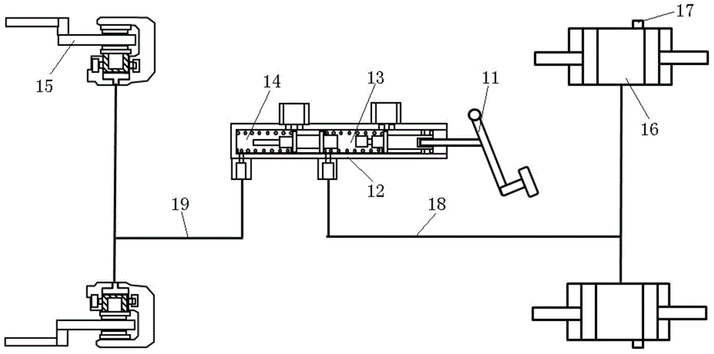
[0029] Such as Figure 4 As shown, the present invention provides a hydraulic braking system manual exhaust auxiliary device, including an electric vacuum pump 101, a recovery oil pot 107, an alarm device 116, a switch 113, a connecting wire 115, a vacuum check valve 103, and a vacuum connecting pipe 102 , exhaust oil pipe 106, vacuum pipe joint 104, drain valve 111, liquid level sensor 112 and magnetic float 110;

[0030] The electric vacuum pump 101 is connected to the vacuum one-way valve 103 through the vacuum connecting pipe 102; one end of the straight air pipe joint 104 is connected to the recovery oil pot 107, and the ...


PUM


Abstract

The invention relates to a manual exhaust auxiliary device for a hydraulic braking system. The auxiliary device comprises an electric vacuum pump, a recycling oilcan, a warning device, a switch, a connecting conducting wire, a vacuum non-return valve, a vacuum connecting pipe, an exhaust oil pipe, a vacuum pipe joint, a bleeder valve, a liquid level sensor and a magnetic float. By adopting vacuum negative pressure principles, after an air bleed screw end is connected into the braking system, the vacuum negative pressure generated by the auxiliary system enables the brake fluid and air in the loop to be pumped to the recycling oilcan, wherein the brake fluid is collected and, the air is exhausted by the electric vacuum pump.

Description

technical field [0001] The invention belongs to the field of brake system maintenance auxiliary equipment, in particular to a hydraulic brake system artificial exhaust auxiliary device. Background technique [0002] In the automotive hydraulic brake system, air is not allowed in the pipeline. Because air is compressible, the existence of air in the pipeline will greatly affect the safety of braking. Therefore, after the brake system is repaired, it must be ensured that all the air in the pipeline is removed. At present, the commonly used method is the artificial exhaust method, that is, the air in the pipeline is compressed by repeatedly stepping on the brake pedal, and then released from the brake wheel cylinder repeatedly from far to near, so as to remove the air from the pipeline. . However, the current vehicle pipeline system is extremely complicated and tortuous, so that air removal becomes extremely difficult, and sometimes the air in the pipeline cannot be eliminate...

Claims


Application Information

Patent Timeline
IPC IPC(8): B60T17/00B60S5/00
CPCB60S5/00B60T17/221
Inventor 张超黄从奎叶飞郑朋辉
Owner ANHUI JIANGHUAI AUTOMOBILE GRP CORP LTD
Why Eureka
Try Eureka