Pre-turbine fluid compression and release system

A fluid and scaling technology, applied in the direction of machines/engines, internal combustion piston engines, mechanical equipment, etc., can solve the problems of manual rotation and self-rotation, etc., and achieve the effect of continuously variable volume, simple structure and reasonable design

Inactive Publication Date: 2015-05-06
范光鑫
View PDF6 Cites 0 Cited by
  • Summary
  • Abstract
  • Description
  • Claims
  • Application Information

AI Technical Summary

Problems solved by technology

[0003] After searching the existing literature, it is found that the patent application number is 200810203032.6, which is called the patented technology of the turbocharger device that uses the rotation of the partition to adjust the volume of the exhaust pipe. It provides a continuous variable volume of the exhaust pipe by using a rotating plate. technology, but its rotation needs to be done manually, and it cannot achieve self-rotation

Method used


Image

  • Pre-turbine fluid compression and release system
  • Pre-turbine fluid compression and release system
  • Pre-turbine fluid compression and release system

Examples


Embodiment

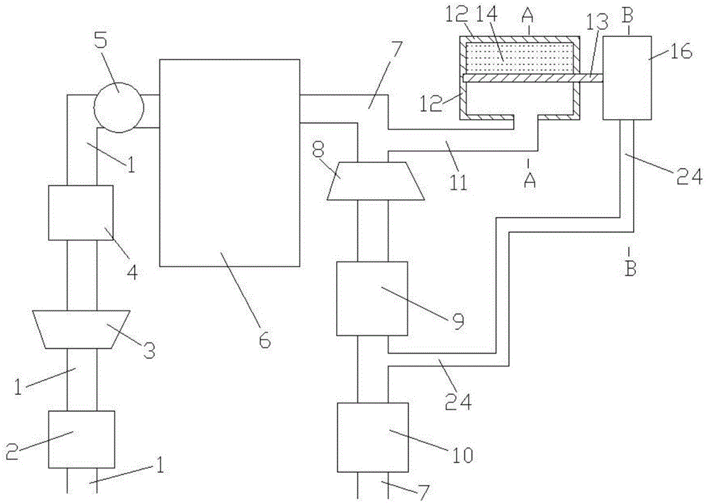
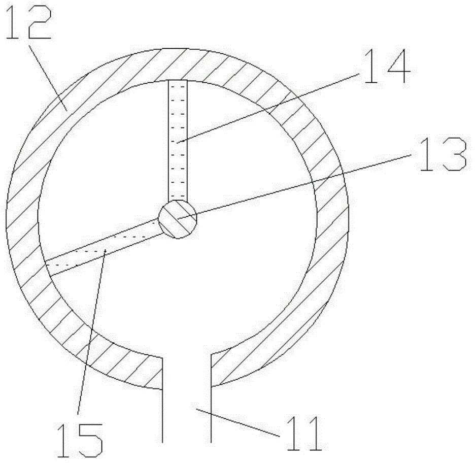
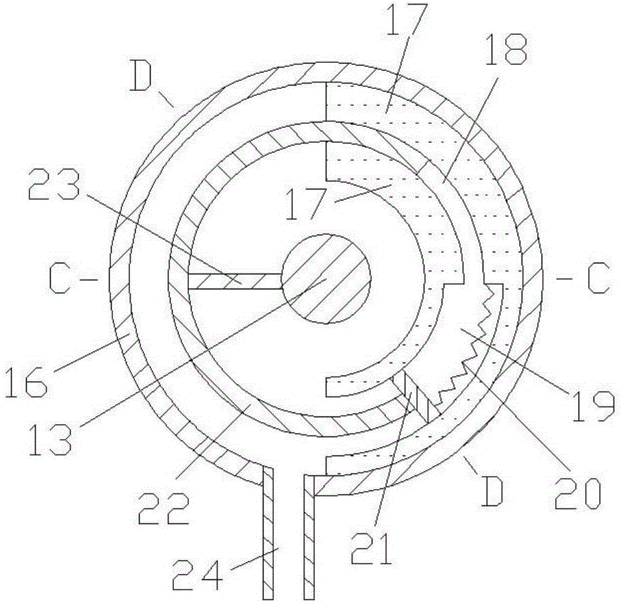
[0015] Examples of the present invention are Figure 1 to Figure 5 As shown, the present invention includes engine intake pipe 1, air filter 2, compressor 3, intercooler 4, throttle valve 5, engine 6, engine exhaust pipe 7, turbine 8, catalytic package 9, muffler 10, first Connecting pipe 11, adjusting chamber 12, rotating shaft 13, rotating plate 14, fixing plate 15, control chamber 16, fixing body 17, first inner pipe 18, second inner pipe 19, spring 20, separator 21, rotating body 22 , connecting plate 23, second connecting pipe 24, the air outlet of engine intake pipe 1 is connected with the air intake of engine 6, the air outlet of engine exhaust pipe 7 is connected with the exhaust passage of engine 6, air filter 2, The compressor 3, the intercooler 4, and the throttle valve 5 are sequentially arranged on the engine intake pipe 1, the turbine 8, the catalytic package 9, and the muffler 10 are sequentially arranged on the engine exhaust pipe 7, the first connecting pipe 1...


PUM


Abstract

The invention belongs to the technical field of internal combustion engines and provides a pre-turbine fluid compression and release system. The pre-turbine fluid compression and release system comprises an engine air inlet pipe, a supercharger, an engine, an engine exhaust pipe, a turbine, connecting pipes, an adjusting cavity, a rotary shaft, a rotary plate, a control cavity, internal pipes, a spring and a rotating body. The adjusting cavity and the control cavity are coaxially connected through the rotary shaft. The upper wall face of the second internal pipe is connected with a partition board through the spring. One end of the second connecting pipe is communicated with an inner cavity of the control cavity. The other end of the second connecting pipe is connected with the engine exhaust pipe between a catalysis bag and a silencer. When the engine operates on a high-speed working condition, the pre-turbine exhaust volume is large, pumping loss is small, and oil consumption is low; when the engine operates on a low-speed working condition, the pre-turbine exhaust volume is small, pulse energy can be fully utilized, and oil consumption is low. The pre-turbine fluid compression and release system is reasonable in design, simple in structure and applicable to optimization design of a turbine supercharged engine exhaust system.

Description

technical field [0001] The invention belongs to the technical field of internal combustion engines, and in particular relates to a swirl prefluid scaling system capable of self-adjusting the volume of an exhaust pipe of a supercharged engine. Background technique [0002] The turbocharging system mainly includes a pulse supercharging system and a constant pressure supercharging system. In the constant-pressure supercharging system, each cylinder shares a large-volume exhaust pipe. The structure of the exhaust pipe system is relatively simple. The pressure in the exhaust pipe is basically kept constant, and the pressure is only related to the load and speed of the engine. The constant pressure supercharging system has less pumping loss, higher turbine efficiency and better performance under high-speed conditions; however, it cannot fully utilize the exhaust pulse energy under low-speed conditions. Pulse supercharging system, according to the firing sequence of each cylinder,...

Claims


Application Information

Patent Timeline
Patent Type & Authority Applications(China)
IPC IPC(8): F02B37/12
CPCY02T10/12
Inventor 范光鑫
Owner 范光鑫
Why Eureka
Try Eureka