An information collection device, electronic equipment and angle control method

A technology for information collection and electronic equipment, which is used in electrical digital data processing, computer monitor casings, instruments, etc. It can solve the problems of fixed angle and non-automatic adjustment of the angle, and achieve the effect of avoiding the wear and tear of the connecting line.

Active Publication Date: 2019-06-25
LENOVO (BEIJING) LTD
View PDF6 Cites 0 Cited by
  • Summary
  • Abstract
  • Description
  • Claims
  • Application Information

AI Technical Summary

Problems solved by technology

[0007] The embodiment of the present application solves the technical problem that the angle of the information collection device integrated on the electronic device in the prior art is fixed and the angle cannot be automatically adjusted by providing an information collection device, electronic equipment and method

Method used


Image

  • An information collection device, electronic equipment and angle control method
  • An information collection device, electronic equipment and angle control method
  • An information collection device, electronic equipment and angle control method

Examples


Embodiment 1

[0053] In Embodiment 1, an information collection device is provided, which is rotatably arranged on an electronic device. In practical applications, the electronic device can be a mobile phone, a notebook, a tablet computer, a desktop computer, and other electronic devices. In this embodiment No longer list them one by one.

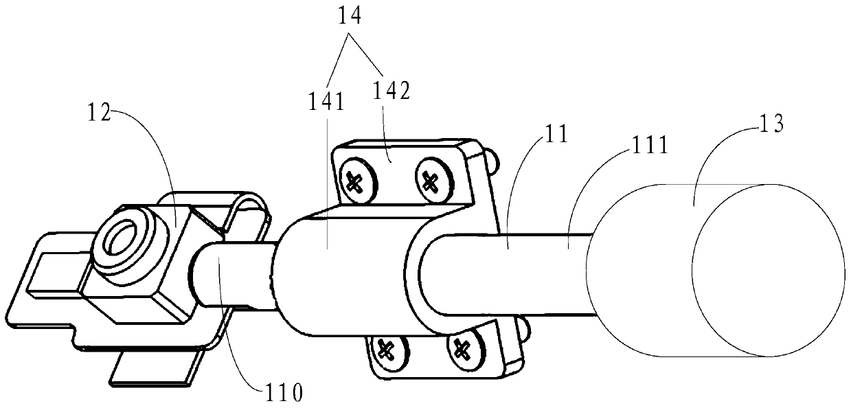
[0054] Please refer to figure 1 , figure 1 It is a schematic structural diagram of the information collection device in Embodiment 1 of the present application, and the device includes:

[0055] The rotating shaft 11 includes a first end 110 and a second end 111 opposite to the first end 110;

[0056] An information collection unit 12, fixedly connected to the first end 110;

[0057] a control unit 13, connected to the second end 111;

[0058] Wherein, when the control unit 13 receives a first trigger signal, the control unit 13 generates and executes an angle adjustment command to drive the rotating shaft 11 to rotate, and then drives the informatio...

Embodiment 2

[0094] An electronic device is provided in Embodiment 2. In practical applications, the electronic device may be a mobile phone, a notebook, a tablet computer, a desktop computer, etc., and will not be listed one by one in this embodiment.

[0095] Please refer to Figure 4 , Figure 4 It is a schematic structural diagram of the electronic device in Embodiment 2 of the present application, and the electronic device includes:

[0096] Chassis 401;

[0097]An information collection device 402 is arranged on the casing 401;

[0098] A processing unit 403 with an information processing function is connected to the information collection device 402 for receiving and processing the collected information collected by the information collection device 402 .

Embodiment 3

[0100] Embodiment 3 provides an angle control method, which is applied to the information collection device described in Embodiment 1. Please refer to Figure 5 , Figure 5 It is a flow chart of the angle control method in Embodiment 3 of the present application, and the method includes:

[0101] Step S501, the control unit 13 receives a first trigger signal;

[0102] Step S502, the control unit 13 generates an angle adjustment instruction based on the first trigger signal;

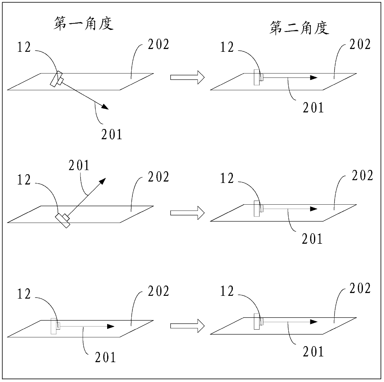
[0103] Step S503, the control unit 13 executes the angle adjustment instruction to drive the rotating shaft 11 to rotate, and then drives the information collection unit 12 to adjust from the current first angle to a third angle different from the first angle. Two angles.

[0104] In the embodiment of the present application, the specific implementation process of the control unit 13 receiving a first trigger signal is as follows:

[0105] When the information collection unit 12 receives a startup ins...


PUM


Abstract

The invention discloses an information collection device, an electronic device and a method. The information collection device is rotatably arranged on the electronic device and comprises a rotation shaft, an information collection unit and a control unit. The rotation shaft comprises a first end and a second end opposite to the first end. The information collection unit is fixedly connected with the first end. The control unit is connected with the second end. When the control unit receives a first trigger signal, the control unit generates and executing an angle adjusting command, so that the rotation shaft is driven to rotate, and the information collection unit is driven to be adjusted to the second angle different from a current first angle from the current first angle. By means of the information collection device, the electronic device and the method, the technical problem that in the prior art, the angle of the information collection device integrated with the electronic device is fixed and can not be automatically adjusted is solved.

Description

technical field [0001] The invention relates to the electromechanical field, in particular to an information collection device, electronic equipment and method. Background technique [0002] With the rapid development of electronic technology, people's life is more and more closely connected with the network and various electronic products with different functions, and with the improvement of living standards, electronic products such as laptops, PADs, and smart phones widespread popularity. [0003] At present, most electronic products are integrated with information collection devices such as cameras and microphones, and users can use the cameras and microphones to make voice and video calls with other users. [0004] However, in the process of realizing the technical solution of the invention in the embodiment of the present application, the inventor of the present application found that the above-mentioned technology has at least the following technical problems: [00...

Claims


Application Information

Patent Timeline
Patent Type & Authority Patents(China)
IPC IPC(8): G06F1/16
CPCG06F1/1607
Inventor 宁柯军
Owner LENOVO (BEIJING) LTD
Why Eureka
Try Eureka