Frame splicing method and device

A picture splicing and picture technology, which is applied in the direction of TV, color TV parts, closed-circuit television system, etc., can solve the problems of serious picture loss and cumbersome picture splicing, etc.

Inactive Publication Date: 2015-05-06
SHENZHEN LAUNCH DIGITAL TECH
View PDF6 Cites 16 Cited by
  • Summary
  • Abstract
  • Description
  • Claims
  • Application Information

AI Technical Summary

Problems solved by technology

[0004] The purpose of the present invention is to provide a method of splicing images according to the video signal priority to save the video signal pi

Method used


Image

  • Frame splicing method and device
  • Frame splicing method and device
  • Frame splicing method and device

Examples


Embodiment Construction

[0024] In order to make the object, technical solution and advantages of the present invention clearer, the present invention will be further described in detail below in conjunction with the accompanying drawings and embodiments. It should be understood that the specific embodiments described here are only used to explain the present invention, not to limit the present invention.

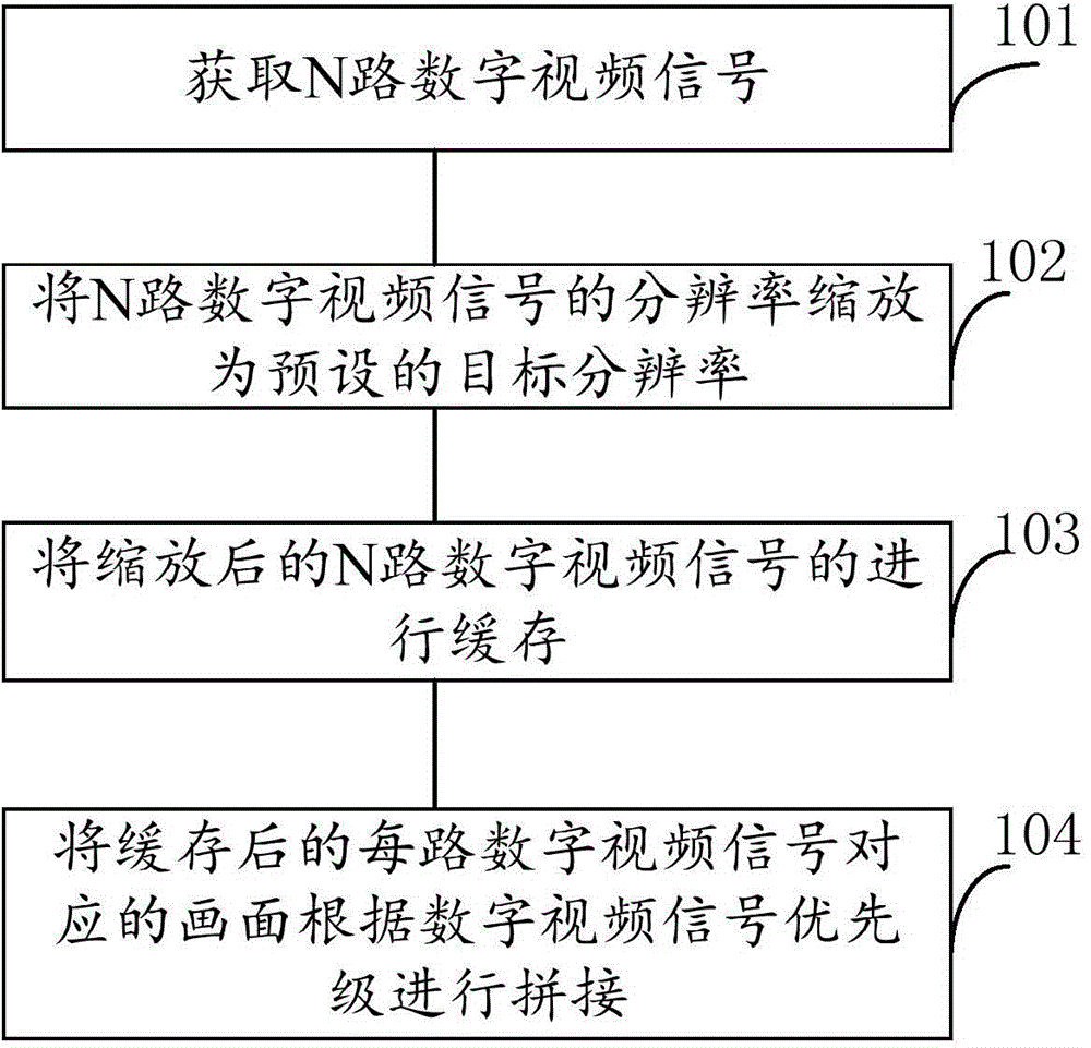
[0025] figure 1 The implementation process of a screen splicing method provided by the embodiment of the present invention is shown, and the details are as follows:

[0026] Step 101. Acquire N channels of digital video signals.

[0027] Specifically, video signals are acquired from N video sources, where N is a natural number greater than 1. For example, video signals are obtained from 8-channel SDI (Serial Digital Interface, digital component serial interface) video sources. Of course, the video source can also be CVBS (Composite Video Broadcast Signal, composite TV broadcast signal), VGA (Vid...


PUM


Abstract

The present invention belongs to the technical field of video monitoring and provides a frame splicing method and device.The frame splicing method comprises: zooming multiple video signals; caching the zoomed video signals; and splicing frames corresponding to the cached multiple digital video signals according to priority of the digital video signals so as to achieve splicing of multiple frames. Since the multiple videos are zoomed and spliced once, the quality loss in frame zooming is reduced and the splicing is easy and convenient.

Description

technical field [0001] The invention belongs to the technical field of video surveillance, and in particular relates to a method and device for splicing pictures. Background technique [0002] At this stage, the use of screen splicing is relatively common. In security monitoring, especially in the case of multiple video inputs, if the viewer can see all the screens at the same time, it is a good idea to splice multiple screens into one screen. choose. In addition, in the court filing system, multiple channels of video need to be recorded at the same time. If splicing is not performed, the multiple channels of video are recorded separately, and the archive is easily tampered with. [0003] The more common splicing method now is the method of cascading splicing. This method usually can only splice 2-way video images. If multi-channel video image splicing is required, multiple 2-way splicing and multiple zooming are required. For example, if you need For 8-channel picture spl...

Claims


Application Information

Patent Timeline
IPC IPC(8): H04N7/18H04N5/262
Inventor 梁洪军谢南斌肖俊陈强
Owner SHENZHEN LAUNCH DIGITAL TECH
Why Eureka
Try Eureka