IC chip shearing equipment with floating device

A technology of shearing equipment and floating device, used in metal processing and other directions, can solve problems such as casualties and low efficiency, and achieve the effects of improving production efficiency, avoiding collection, and preventing accidental casualties.

Inactive Publication Date: 2015-05-13
CHIZHOU RICHSEMI ELECTRONICS
View PDF6 Cites 1 Cited by
  • Summary
  • Abstract
  • Description
  • Claims
  • Application Information

AI Technical Summary

Problems solved by technology

[0003] The technical problem to be solved by the present invention is to provide an IC chip cutting device with a floating device to solve the problems of low efficiency and casualties

Method used


Image

  • IC chip shearing equipment with floating device

Examples


Embodiment Construction

[0023] In the following, numerous specific details are set forth in order to provide a thorough understanding of the concepts underlying the described embodiments. It will be apparent, however, to one skilled in the art that the described embodiments may be practiced without some or all of these specific details. In other instances, well known processing steps have not been described in detail.

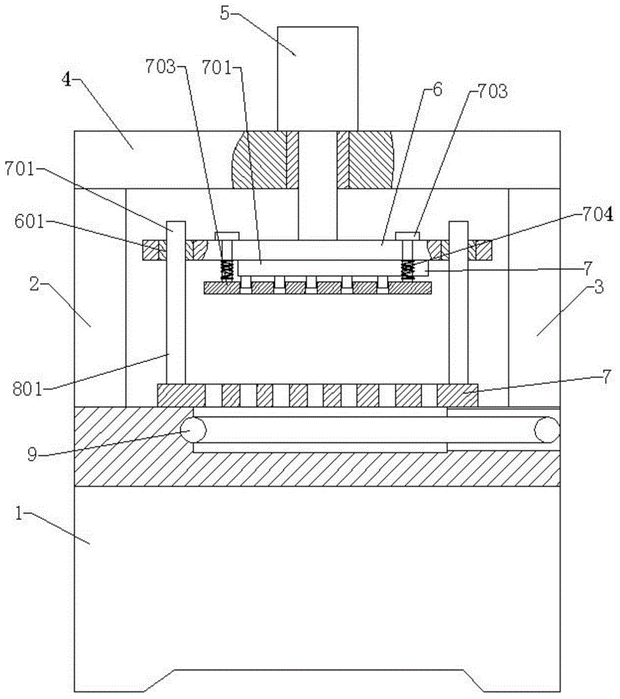
[0024] Such as figure 1 As shown, it includes machine base 1, left support base 2, right support base 3, top plate 4, hydraulic cylinder 5, upper template 6, upper floating shear die 7, lower shear die 8, conveyor 9, the left The support base 2 is located at the left end of the top center of the base 1, and the two are connected by welding. The right support base 3 is located at the right end of the top center of the base 1, and the two are connected by welding. The top plate 4 is located between the left support base 2 and the right support base. 3 at the center of the top, which i...


PUM


Abstract

The invention discloses IC chip shearing equipment with a floating device. The IC chip shearing equipment with the floating device comprises an engine base which comprises a left supporting seat, a right supporting seat, a roof, a hydraulic cylinder, an upper die plate, an upper floating shearing die, a lower shearing die and a conveyor; compared with the prior art, resin which contains the IC chip is put in the lower shearing die, the upper floating shearing die which is pushed to go down through hydraulic pressure and the lower shearing die together shear the resin which contains the IC chip into a single piece, the single piece falls on the top of the conveyor, and the single piece of the IC chip is conveyed out of the equipment through the conveyor to conduct tidying up and packaging manually. Therefore, the production efficiency is improved, the manual collection is avoided, and the occurrence of accidental casualty is prevented.

Description

technical field [0001] The invention relates to a die-cutting device, in particular to an IC chip cutting device with a floating device. Background technique [0002] With the development of science and technology, electronic products are becoming more and more advanced and smaller and smaller. The root of the development of electronic products lies in the extensive use of IC chips. Since electronic chips are extremely small, in order to facilitate the use of IC chips, they need to be wrapped in chips. A layer of resin, usually a piece of resin is wrapped with several chips, which are cut into a single piece by a processing device. Currently, it is cut through a mold, but the IC chip is small in size, and after being cut into a single piece The collection is inconvenient, resulting in low efficiency, and by manual collection, the upper mold will accidentally drop, causing serious casualties. In view of the above defects, it is necessary to design an IC chip cutting device wi...

Claims


Application Information

Patent Timeline
Patent Type & Authority Applications(China)
IPC IPC(8): B26F1/40B26F1/44
CPCB26F1/38B26D5/12B26D2007/322B26F1/44
Inventor 陈友兵
Owner CHIZHOU RICHSEMI ELECTRONICS
Why Eureka
Try Eureka