Supercharge Your Innovation With Domain-Expert AI Agents!

a self-locking device

A technology of self-locking device and self-locking groove, which is applied in the direction of door/window protection device, anti-insect, window/door, etc. It can solve the problems of inability to realize free opening or processing, inability to form large-scale, inability to lock and lock, etc., to achieve Overcome the effect of not being able to automatically lock, save the button to unlock, and save the button to lock

Active Publication Date: 2016-07-13
郝建松
View PDF6 Cites 0 Cited by
  • Summary
  • Abstract
  • Description
  • Claims
  • Application Information

AI Technical Summary

Problems solved by technology

[0002] At present, the so-called invisible screen doors and windows are screen doors and windows with automatic rewinding of the screen; the frame is tightly attached to the door and window frame, and the tension beam connecting the screen is pulled down when it is used, and the screen will automatically return when not in use. Rolled into the yarn box, the device needs to be locked and opened when the pull beam is pulled down and rewound. The existing locking and opening mechanisms mainly include magnetic suction, hooks, etc.; magnetic suction is the attraction between the beam and the bottom The frame is fixed, this method will reduce the magnetism of the magnet if used for a long time, resulting in the failure to lock or the lock is not firm; the hook method is to use a hook to fix the beam and the bottom frame, this method is not flexible and cannot automatically lock the screen window And the merging is not reliable, and other locking methods that realize the same function on the market are very complicated and costly, and cannot be mass-produced; for example, the patent No. 201020270205. It uses a series of device components such as hooks, springs, and buttons to realize the window locking function, which is not only costly, but also cannot be opened freely or is very cumbersome to process, which reduces user experience

Method used


Image

  • a self-locking device
  • a self-locking device
  • a self-locking device

Examples


Embodiment Construction

[0027] The present invention will be described in further detail below in conjunction with the accompanying drawings and specific embodiments, and the implementation scope of the present invention is not limited thereto.

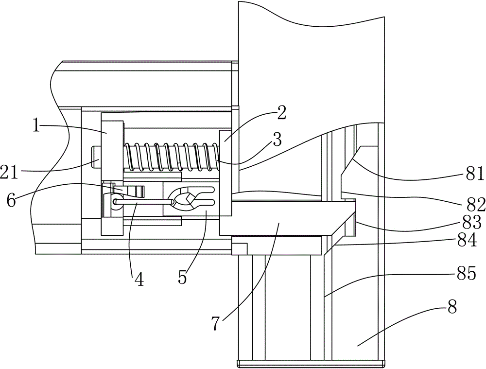
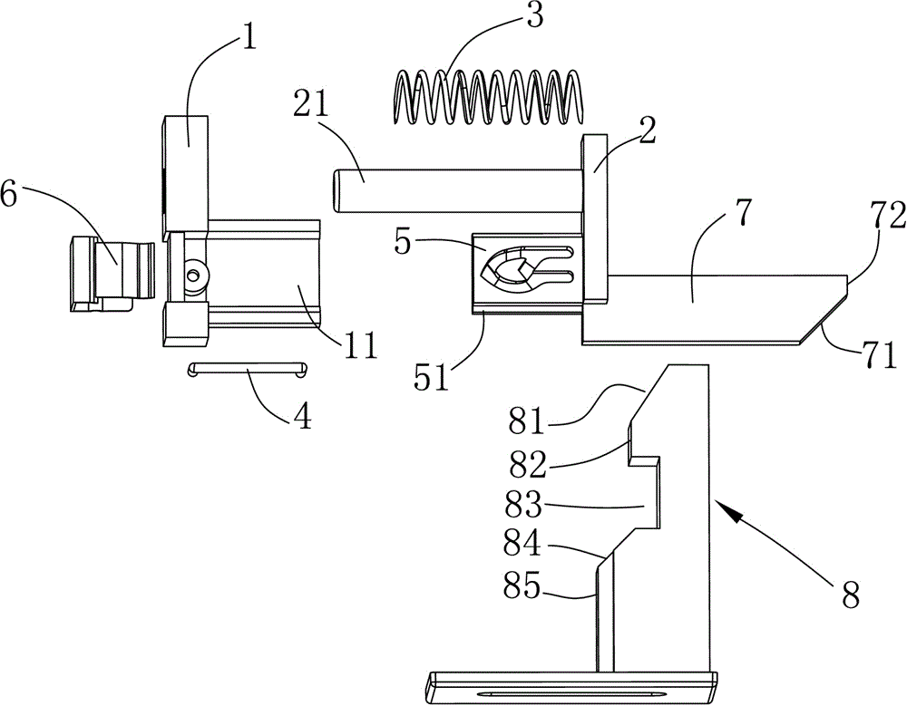
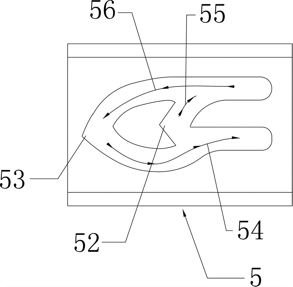
[0028] Such as Figure 1 to Figure 8 As shown, a self-locking device described in this embodiment includes a first abutment plate 1, a second abutment plate 2, a spring 3 arranged between the first abutment plate 1 and the second abutment plate 2, and an end shaft Connected to the track hook 4 of the first butt plate 1; a track block 5 cooperating with the track hook 4 is extended from one side of the second butt plate 2, and a free track block 5 is extended from the other side of the second butt plate 2 The first slider 7 with a first slope 71 at the end; the self-locking device also includes a lock block 8 that cooperates with the first slider 7; the lock block 8 includes a second slope 81, located on the second slope The first straight surface 82 at the ...


PUM


Abstract

The invention relates to a self-locking device which comprises a first abutting plate, a second abutting plate, a spring arranged between the first abutting plate and the second abutting plate, and a rail ditch with one end connected to the first abutting plate through a shaft. One side of the second abutting plate extends outwards to form a rail block matched with a rail hook, and the other side of the second abutting plate extends outwards to form a first slide block with a first inclined face at the free end. The self-locking device further comprises a locking block matched with the first slide block. A guide groove connected with the other end of the rail hook in a sliding mode is formed in the rail block. By means of the self-locking device, the defect that an existing roller shutter window and door can not be automatically locked is overcome, and the automatic locking is completely achieved; the self-locking device is simple in structure, easy to produce, low in cost, capable of being produced on a large scale and remarkable in social and economic benefit; the self-locking device is compact in structure, a beam and a bottom frame of the self-locking device firmly abut against each other, and gaps can be effectively avoided; the self-locking device is easy and convenient to use and can be easily accepted by consumers, and the user experience is high.

Description

technical field [0001] The invention relates to a self-locking device. Background technique [0002] At present, the so-called invisible screen doors and windows are screen doors and windows with automatic rewinding of the screen; the frame is tightly attached to the door and window frame, and the tension beam connecting the screen is pulled down when it is used, and the screen will automatically return when not in use. Rolled into the yarn box, the device needs to be locked and opened when the pull beam is pulled down and rewound. The existing locking and opening mechanisms mainly include magnetic suction, hooks, etc.; magnetic suction is the attraction between the beam and the bottom The frame is fixed, this method will reduce the magnetism of the magnet if used for a long time, resulting in the failure to lock or the lock is not firm; the hook method is to use a hook to fix the beam and the bottom frame, this method is not flexible and cannot automatically lock the screen...

Claims


Application Information

Patent Timeline
Patent Type & Authority Patents(China)
IPC IPC(8): E06B9/80E06B9/54
Inventor 郝建松
Owner 郝建松
Features
  • R&D
  • Intellectual Property
  • Life Sciences
  • Materials
  • Tech Scout
  • Unparalleled Data Quality
  • Higher Quality Content
  • 60% Fewer Hallucinations
Learn More