Eureka AIR delivers breakthrough ideas for toughest innovation challenges, trusted by R&D personnel around the world.

A retractable magneto-rheological damper with built-in permanent magnets in double rods

A magneto-rheological damper and permanent magnet technology, which is applied in the direction of shock absorbers, shock absorbers, springs/shock absorbers, etc., can solve the problem of the increase in the size of the damper, the lack of reach, and the performance of the magneto-rheological damper Drop and other problems, to achieve the effect of improving reliability, high magnetic energy product and coercive force, and increasing the working stroke

Inactive Publication Date: 2016-07-06
CHINA UNIV OF MINING & TECH
View PDF7 Cites 0 Cited by
  • Summary
  • Abstract
  • Description
  • Claims
  • Application Information

AI Technical Summary

Problems solved by technology

[0003] The magneto-rheological damper is an intelligent damping device. The existing damper generally places the electromagnetic coil on the piston, and adjusts the damping force by changing the magnitude of the current, but the coil will generate A lot of heat, under such working conditions, the performance of the magneto-rheological damper will decrease, and the expected effect will not be achieved; the working stroke of the magnetorheological damper with two rods is limited by the length of the working cylinder, blindly Increasing the length of the working cylinder or increasing the length of the piston rod will increase the overall size of the damper

Method used


Image

  • A retractable magneto-rheological damper with built-in permanent magnets in double rods
  • A retractable magneto-rheological damper with built-in permanent magnets in double rods
  • A retractable magneto-rheological damper with built-in permanent magnets in double rods

Examples


Embodiment Construction

[0024] The present invention will be further described below in conjunction with accompanying drawing.

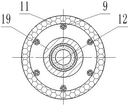
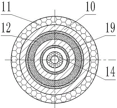
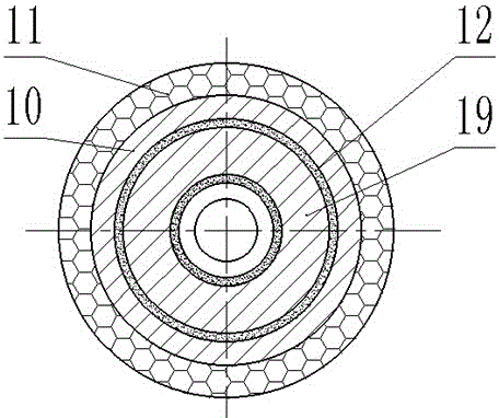
[0025] Such as Figure 1 to Figure 4 As shown, a retractable magneto-rheological damper with built-in permanent magnets in double-outlet rods includes movable earrings 1 at both ends of the piston rod 2, a fixed outer cylinder 10, and an outer shell connected to the power supply 16 arranged on the outer layer of the fixed outer cylinder 10. Set electromagnetic coil 11, the piston 13 that is symmetrically distributed in piston rod 2 two ends; Described fixed outer cylinder 10 is respectively connected with fixed outer cylinder left end cover 20 and fixed outer cylinder right end cover 18 by hexagon socket head cap screw 2;

[0026] It also includes two built-in permanent magnets 14 symmetrically distributed on the piston 13. During the movement, the permanent magnets do not need to be energized, which reduces the internal heating problem; the movable inner cylinder 19 is loc...


PUM


Abstract

The invention discloses a double-outlet-rod telescopic magneto-rheological damper with built-in permanent magnets. The double-outlet-rod telescopic magneto-rheological damper comprises the two built-in permanent magnets (14) and a movable inner cylinder (19), wherein the two built-in permanent magnets (14) are symmetrically distributed on a piston (13), the movable inner cylinder (19) is arranged in a center hole of a fixed outer cylinder (10), the external diameters of the two ends of the movable inner cylinder (19) are smaller than the internal diameters of a left end cover (20) and a right end cover (18) of the fixed outer cylinder, and the external diameter of the middle of the movable inner cylinder (19) is larger than the inner diameter of the movable inner cylinder (19). The damper is internally provided with the two NdFeB permanent magnets in series and externally provided with an electromagnet, the permanent magnet do not need to be powered on, the heat dissipating problem does not exist in the damper, the using reliability of magneto-rheological liquid is integrally improved; meanwhile, by means of the double-outlet-rod structure with the movable inner cylinder, a gas compensation device does not need to be additionally arranged, the working stroke is increased, the stroke of the damper is greatly increased on the original basis due to the fact that the inner cylinder is movable, and a very large advantage is achieved on the large-stroke damper.

Description

technical field [0001] The invention relates to a magneto-rheological damper with double-outlet rods, in particular to a retractable magneto-rheological damper with built-in permanent magnets in double-outlet rods, which belongs to the technical field of magnetorheological fluid. Background technique [0002] Magnetorheological fluid is a new type of magnetic functional material. When there is no external magnetic field, it behaves as a well-flowing Newtonian fluid. However, under the action of an external magnetic field, the rheological properties of the fluid change dramatically, showing mechanical properties similar to solids. And the viscosity change is continuous and reversible, that is, once the magnetic field is removed, it becomes a flowable liquid again. The continuous, reversible, rapid and easy-to-control characteristics of magnetorheological fluid effects make magnetorheological fluid mechanical devices have very wide application prospects in aviation, aerospace,...

Claims


Application Information

Patent Timeline
Patent Type & Authority Patents(China)
IPC IPC(8): F16F9/53
CPCF16F9/185F16F9/3235F16F9/3242F16F9/369F16F9/535
Inventor 刘新华彭俊泉任衍坤郑显华刘晶晶王冬冬李生鹏陈小虎张秋香
Owner CHINA UNIV OF MINING & TECH
Why Eureka
Eureka Blog
Learn More