
Self-lubricating gear

A self-lubricating, gear technology, applied in the direction of gear lubrication/cooling, belt/chain/gear, components with teeth, etc., can solve the problems of poor gear lubrication, reduce the service life of gears, etc., and achieve the effect of improving the lubrication effect

Active Publication Date: 2015-05-13
YANCHENG INST OF TECH
View PDF4 Cites 46 Cited by
  • Summary
  • Abstract
  • Description
  • Claims
  • Application Information

AI Technical Summary

Benefits of technology

This patented technology helps prevent damage caused by excessive wear on parts like bearings used for transmissions. By expanding certain materials with their own specific properties when they are compressed into tubes called “self-lubripping” devices, these new material becomes more effective at protecting them from being worn down over time compared to traditional methods such as grease injection.

Problems solved by technology

This patented technical problem addressed by this patents relates to improving the lubrification process for gears during use without causing excessive wear on them caused by lacking sufficient lubricity.

Method used


Image

  • Self-lubricating gear
  • Self-lubricating gear
  • Self-lubricating gear

Examples


Embodiment Construction

[0020] Below in conjunction with accompanying drawing and specific embodiment the present invention is described in further detail:

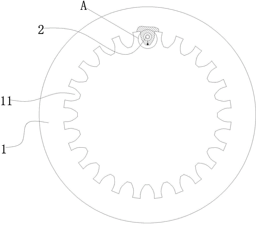
[0021] Such as figure 1 As shown, a self-lubricating gear, the gear 1 is an internal gear. There are six gear teeth 11 in the gear that are provided with self-lubricating device 2, and the six gear teeth that are provided with self-lubricating device are circumferentially evenly distributed.

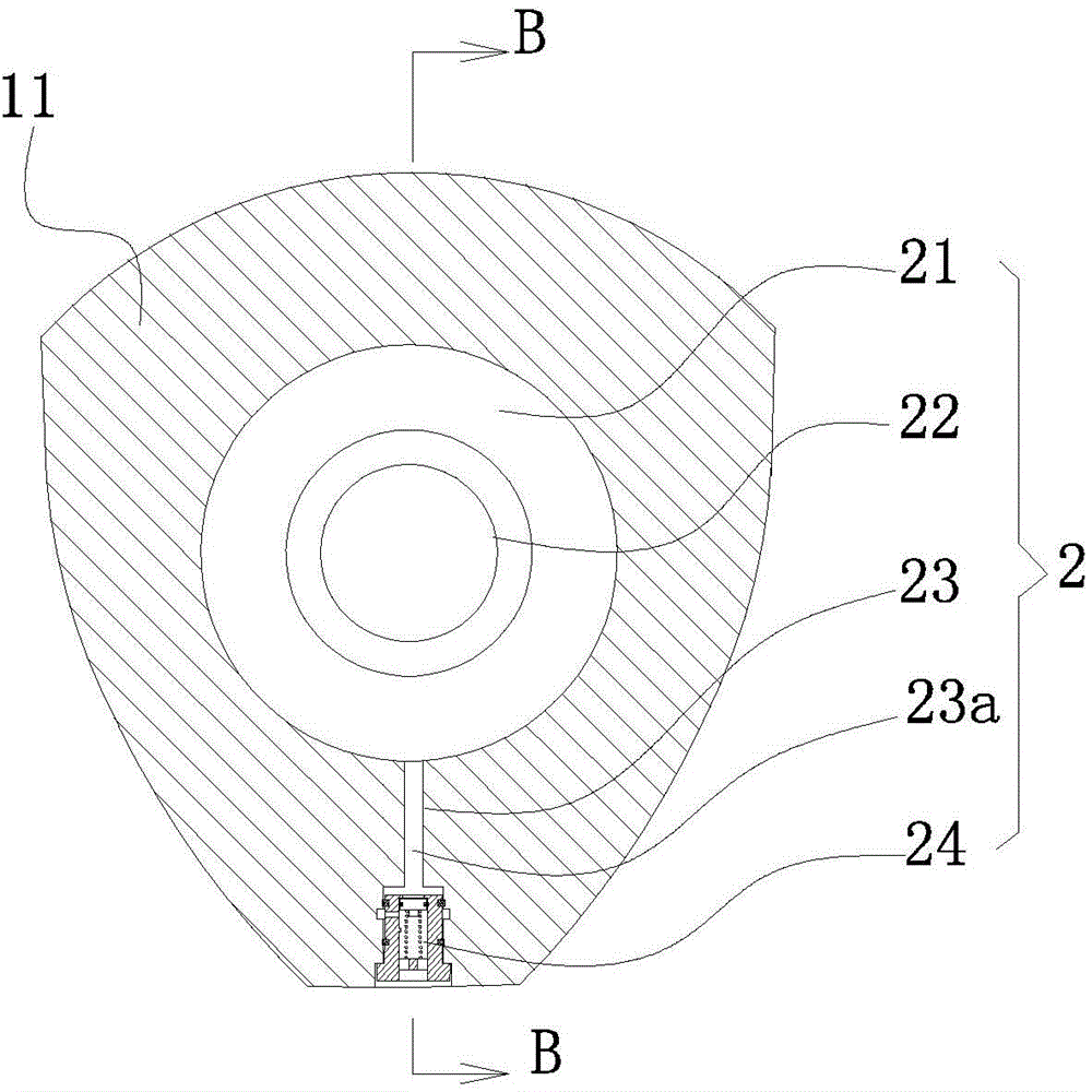
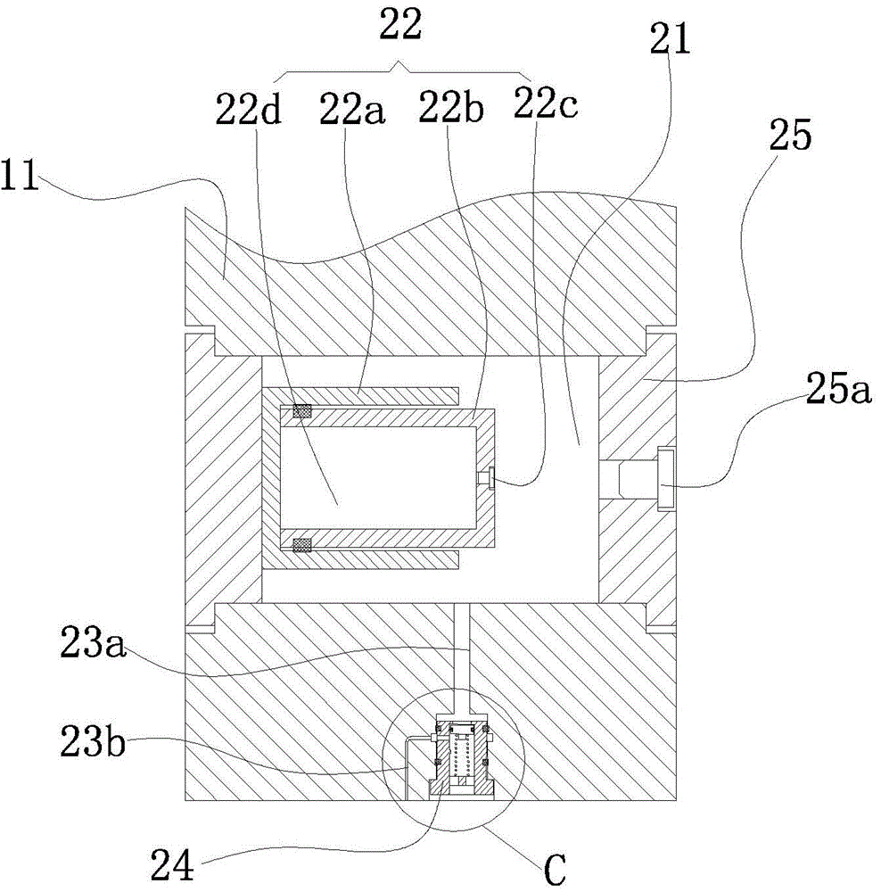
[0022] The self-lubricating device includes an oil storage chamber 21 arranged in the gear teeth, an adaptive telescopic device 22 arranged in the oil storage chamber, a lubricating oil passage 23 arranged in the gear teeth and an automatic opening and closing of the lubricating oil passage arranged in the gear teeth. Closing device 24. The oil storage chamber is a cylindrical cavity parallel to the axis of the gear. The oil storage chamber runs through both ends of the gear. The two ends of the oil storage chamber are respectively provided with sealin...


PUM


Abstract

The invention discloses a self-lubricating gear. A self-lubrication device is arranged on at least one gear tooth of the gear and comprises an oil storage cavity, an adaptive extensible device and a lubrication oil way. The oil storage cavities are formed in the gear teeth, the adaptive extensible devices are arranged in the oil storage cavities, and the lubrication oil ways are arranged in the gear teeth. One end of each lubrication oil way is communicated with the corresponding oil storage cavity, and the other end of each lubrication oil way is communicated with the cylindrical surface of the top of the corresponding gear tooth. Each adaptive extensible device comprises a fixed sleeve and a slidable sleeve. The fixed sleeves are arranged in the oil storage cavities, and the slidable sleeves are arranged in the fixed sleeves. The fixed sleeves are fixed on the inner walls of the oil storage cavities. One end of each fixed sleeve is closed, and the other end of each fixed sleeve is open. First seal rings are arranged between the inner side faces of the fixed sleeves and the outer side faces of the slidable sleeves. One end of each slidable sleeve is closed, and the other end of each slidable sleeve is open. The open ends of the slidable sleeves face the closed ends of the fixed sleeves. By the self-lubricating gear, the problems of poor gear lubrication and shortening of service life of the gear due to lubrication system failure, lubrication system oil shortage or the like can be solved effectively.

Description


Claims


Application Information

Patent Timeline
Owner YANCHENG INST OF TECH
Learn More