
Ink box for laser printer

A technology of laser printers and printers, applied in optics, electrical recording, instruments, etc., can solve problems such as cumbersome installation process, damage, and complex structure of ink cartridges, and achieve the effect of easy connection and separation, and collision prevention

Inactive Publication Date: 2015-05-13
BEIHAI HESI TECH
View PDF2 Cites 2 Cited by
  • Summary
  • Abstract
  • Description
  • Claims
  • Application Information

AI Technical Summary

Problems solved by technology

The traditional technology needs to connect the protrusions to the ink cartridge by adding some elastic members. Such an ink cartridge has a complicated structure, it is difficult to prevent the uneven rotation of the photosensitive drum, and the installation process is cumbersome. At the same time, the protrusions are exposed at both ends of the ink cartridge, which is easy damaged by collision

Method used


Image

  • Ink box for laser printer
  • Ink box for laser printer
  • Ink box for laser printer

Examples


Embodiment 1

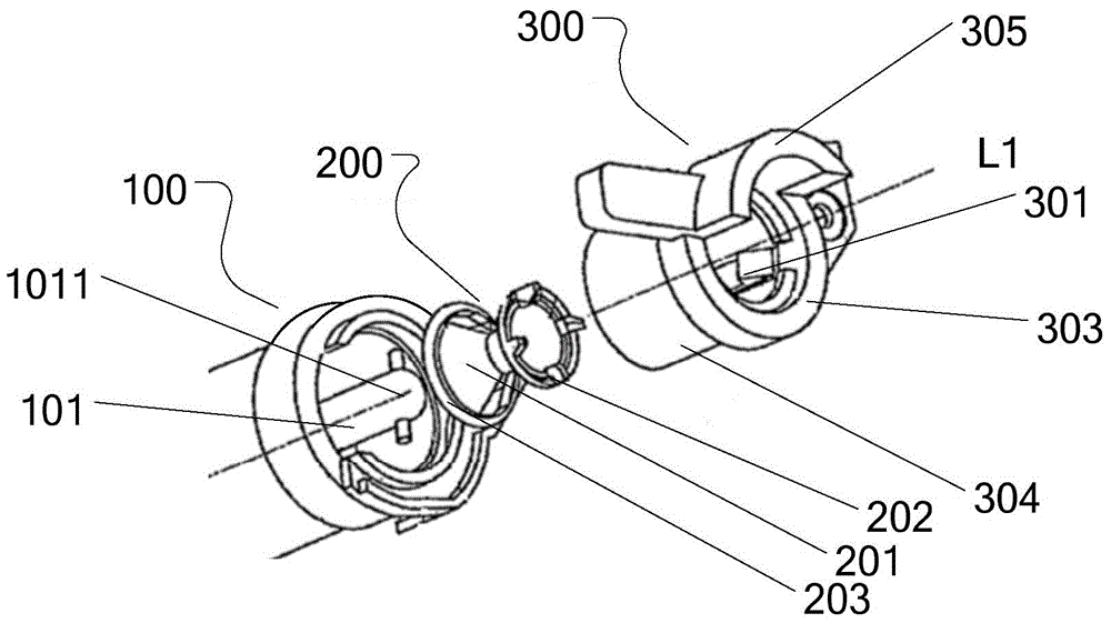
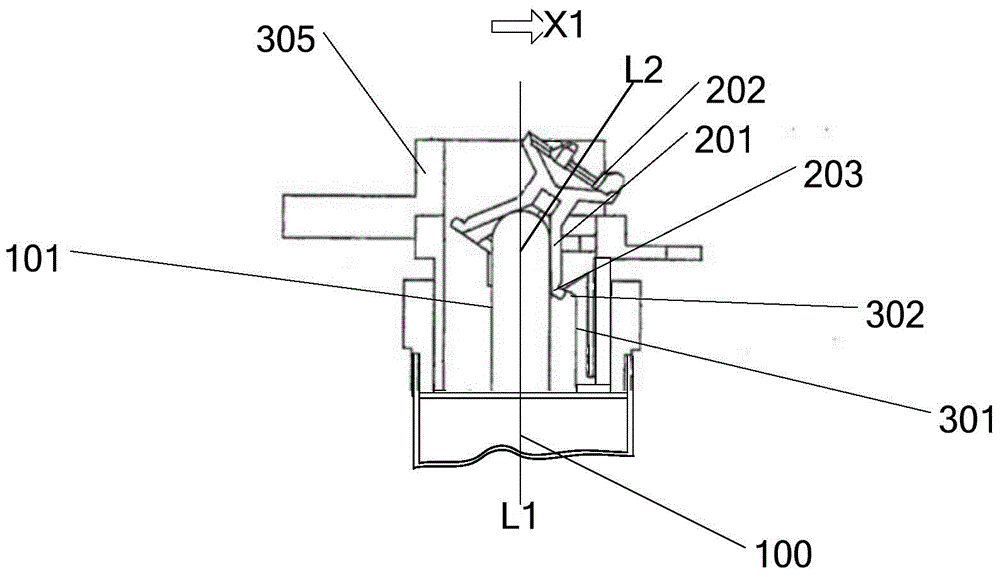
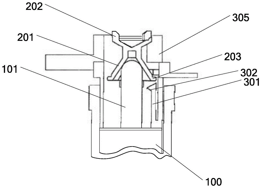
[0020] Such as figure 1 with figure 2 As shown, the laser printer ink cartridge of the present invention includes: a photosensitive drum 100, at least one side of the photosensitive drum 100 is provided with a shaft 101; The free end 202 of the photosensitive drum receives rotational driving force from the printer and rotates; the engaging portion 201 has a flange portion 203 ; the shaft 101 is detachably connected to the printer through the connecting member 200 .

[0021] And the drum receiving part 300, which is ring-shaped and arranged substantially coaxially with the shaft 101, the connecting part 200 is arranged in its inner space, and its inner side wall is provided with a locking part 301, the locking surface 302 of the locking part 301 A part is engaged with the upper surface of the flange portion 201 and at the same time is in contact with the inclined surface of the connector 200 to maintain the inclination angle of the connector 200 . The flange portion 203 is d...

Embodiment 2

[0033]In this embodiment, the locking member 301 is an elastic rib extending perpendicular to the inner surface of the side wall of the drum receiving member 300 . The locking member 301 is provided with an elastic portion. The amount of engagement between the lock piece 301 and the flange portion 203 is reduced. The locking piece 301 is disposed on the most downstream side with respect to the installation direction X1.

[0034] In one of the examples, as Figure 4 As shown, the locking member 301 is arranged upstream relative to the mounting member direction X1. The lock 301 is constituted by a part of the drum support 300 .


PUM


Abstract

The invention discloses an ink box for a laser printer. The ink box comprises a photosensitive drum, a connecting piece and a drum bearing piece, wherein a shaft is arranged on at least one side of the photosensitive drum; the connecting piece comprises a connection part connected with the shaft and a free end used for receiving the rotary driving force from the printer and rotating the photosensitive drum, the connection part is provided with a flange part, and the shaft is detachably connected to the printer through the connecting piece; the drum bearing piece is annular and is roughly coaxial with the shaft, and the connecting piece is arranged in the inner space of the drum bearing piece; a locking piece is arranged on the inner side wall of the drum bearing piece, and a part of the locking surface of the locking piece is connected with the upper surface of the flange part and is also in contact with the inclined plane of the connecting piece to keep the angle of inclination of the connecting piece. The ink box has the advantages of being simple in structure and convenient to mount and dismount, and meanwhile the two ends of the ink box are effectively prevented from collision damage.

Description

technical field [0001] The present invention relates to a printer device, and more particularly provides a printer ink cartridge which is easy to install and disassemble. Background technique [0002] With the gradual improvement of printers, users themselves can detachably install the ink cartridges to the printer. Therefore, the user can perform the maintenance of the equipment by himself without relying on the service personnel. In conventional ink cartridges, the following configurations are known for receiving rotational driving force from a printer to rotate a photosensitive drum. [0003] On the printer side, a rotatable member and a non-circular torsion hole are provided, the rotatable member is used to transmit the driving force of the motor, the torsion hole is arranged at the center of the rotatable member, a plurality of corners are provided and It has a cross section that can rotate integrally with the rotatable member. On the side of the ink cartridge, there...

Claims


Application Information

Patent Timeline
IPC IPC(8): G03G15/08
CPCG03G21/1857G03G21/1814G03G21/1842
Inventor 陈平
Owner BEIHAI HESI TECH
Learn More