Inductive device limiting acoustic oscillations

A technology for induction devices and windings, applied in circuit devices, transformer/inductor noise damping, electrical components, etc., can solve problems such as incompatibility, expensive design requirements, etc., and achieve the effect of reducing vibration

Active Publication Date: 2015-05-13
RENAULT SA
View PDF4 Cites 0 Cited by
  • Summary
  • Abstract
  • Description
  • Claims
  • Application Information

AI Technical Summary

Problems solved by technology

[0005] However, these solutions are expensive and not compatible with the design requirements of low-cost hybrid or electric vehicles

Method used


Image

  • Inductive device limiting acoustic oscillations

Examples


Embodiment Construction

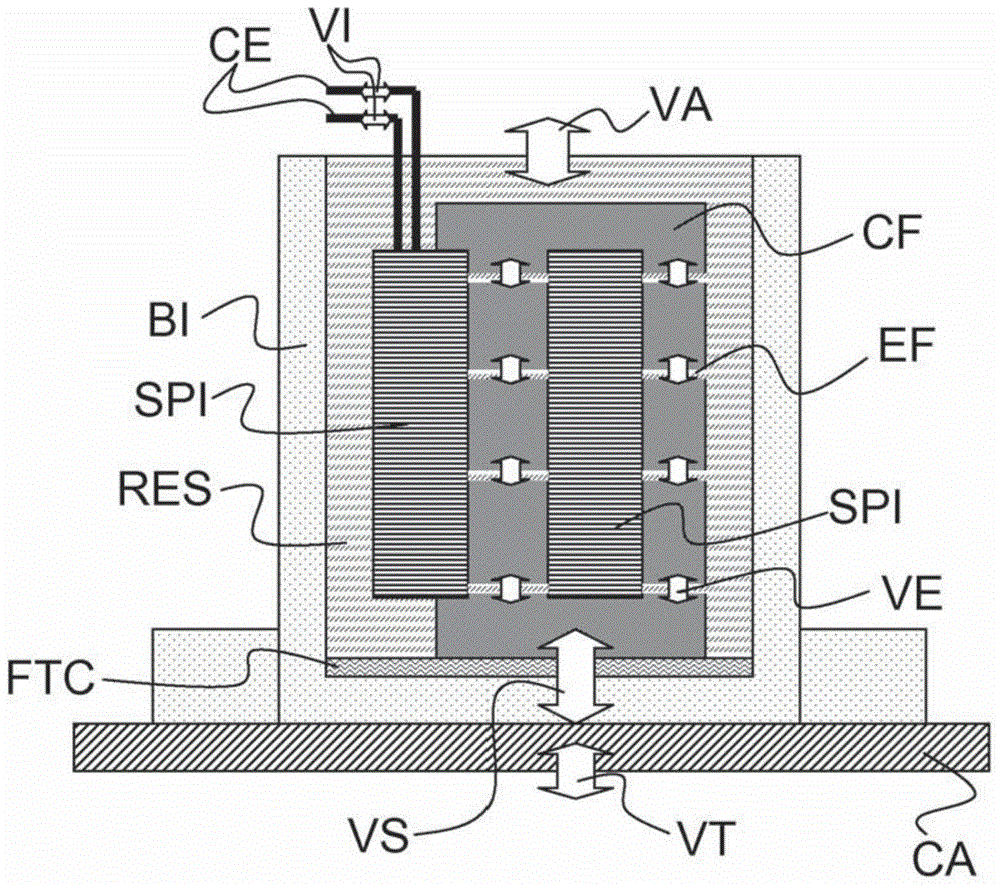
[0023] According to a preferred embodiment of the invention shown in the drawings, the induction device according to the invention has a housing BI formed by an aluminum can. The housing BI is fastened at its lower base by four screws to the housing CA protecting the power electronics module of the electric vehicle charger in the region of the housing CA cooled by the charger's cooling system. This is because in this embodiment of the invention an inductive device is used as inductive for the electric vehicle charger.

[0024] The winding SPI is held vertically in the longitudinal direction within the housing BI and is connected to electrical connectors CE through which high currents with a current variation VI enter and leave when the induction device is used. A ferromagnetic body CF is partially inserted into the winding SPI. The ferromagnetic body is composed of a plurality of ferromagnetic blocks (for example ferrite blocks) separated by a gap EF placed transversely with ...


PUM

PropertyMeasurementUnit
thicknessaaaaaaaaaa
hardnessaaaaaaaaaa
hardnessaaaaaaaaaa

Abstract

The invention relates to an inductive device comprising a winding (SPI) in which a ferromagnetic body (CF) comprising gaps (EF) is inserted, the winding (SPI) being held in a metal casing (BI), and in which a thermally conductive film (FTC) is placed between the ferromagnetic body (CF) and a base of the metal casing (BI), the film (FTC) having a stiffness lower than that of a synthetic resin.

Description

technical field [0001] The present invention relates generally to the field of electrical engineering, and more precisely to an induction device for power electronics, that is to say a current that can withstand, for example, several hundred amperes and can be used in particular for electric vehicles or hybrid A device for powering a charger for a vehicle. Background technique [0002] In a known method, an induction device or induction of this type comprises a winding inside which passes a ferromagnetic body with a gap intended to limit the saturation of the ferromagnetic body as a mechanical air gap. The body is formed, for example, from a plurality of ferromagnetic blocks, eg ferrite blocks, separated from each other by gaps. Both the winding and the ferromagnetic body are inserted into an aluminum can and embedded in resin. The ferromagnetic body is placed directly in contact with the base of the aluminum can to facilitate its cooling. [0003] When the current throug...

Claims


Application Information

Patent Timeline
Patent Type & Authority Applications(China)
IPC IPC(8): H01F27/33
CPCH01F27/33H02J50/10
Inventor L-M·热内L·德勒莫
Owner RENAULT SA
Why Eureka
Try Eureka