A telescopic feeding machine weighing base

A feeding machine, retractable technology, applied in fish farming, application, climate change adaptation, etc., can solve the problems of no weighing function, easy to stop and go, complex structure, etc., to reduce the cost of replacement and update, and to facilitate installation and maintenance The effect of flexibility and convenient installation of sensors

Inactive Publication Date: 2017-05-31
FRESHWATER FISHERIES RES CENT OF CHINESE ACAD OF FISHERY SCI
View PDF12 Cites 0 Cited by
  • Summary
  • Abstract
  • Description
  • Claims
  • Application Information

AI Technical Summary

Problems solved by technology

The working principle of the ordinary feeding machine is to set the timing and feeding gear in advance, and the feeding machine will finish feeding the feed according to the established method. This feeding method can only roughly estimate the amount of feed fed, and cannot scientifically obtain accurate results. The value of the feeding machine without weighing function cannot meet the needs of modern fishery production
Most of the current feeding machines adopt a mechanical control mode. The timing is not accurate and it is easy to stop and go. It is impossible to estimate the wasted feed.
The common feeding machine currently used cannot fully, rationally and scientifically use feed, and cannot accurately grasp the amount of feed, which forms a bottleneck for scientific fish farming and precise control
[0003] In the prior art, the Chinese invention patent (publication number CN 103891664A) discloses an automatic weight feeding platform for feeding machines. This patent can realize weight feeding for ordinary feeding machines, but the structure is complicated and the bracket is fixed. Customized use with the corresponding feeding machine, when changing the feeding machine with different capacity, it is necessary to re-customize the feeding table, and with the growth of the feeding animals, it is necessary to replace the feeding machine regularly, which brings unnecessary troubles

Method used


Image

  • A telescopic feeding machine weighing base
  • A telescopic feeding machine weighing base
  • A telescopic feeding machine weighing base

Examples


Embodiment Construction

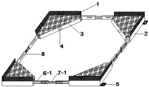
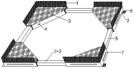
[0020] The present invention will be further described below in conjunction with the accompanying drawings. Such as figure 1 , figure 2 As shown, the weighing base of the retractable feeding machine shown in the present invention mainly includes four triangular boxes 2 of the same specification, and the storage platform 3 on the triangular box is independent, and it is convenient to be stressed when weighing; A baffle plate 1 with a certain height is provided to prevent the feeding machine from toppling over; each triangular box has an outlet 4 for a load cell; every two triangular boxes are connected by a telescopic slide rail or a slide bar; the telescopic slide rail consists of two An outer chute 6-1 and an inner slide block 7-1 form, and the telescopic slide bar is formed 7-2 by two mechanical chute 6-2 and a strip slide bar.

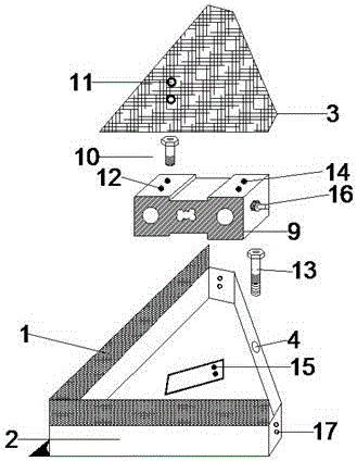
[0021] Before installing the base, you need to complete the assembly of the triangular box. The triangular box is as follows: image 3 , Figu...


PUM


Abstract

The invention discloses a telescopic feeder weighing base which comprises a plurality of weighing modules and a plurality of telescopic connecting devices. The weighing modules are connected through the telescopic connecting devices. A feeder is placed on the plane of the weighing modules. The number of the weighing modules is four, and each weighing module comprises a triangular box and a weighing sensor, wherein each weighing sensor is placed in the corresponding triangular box and covered with a storage platform; each triangular box is a right-angle triangular box, and the right-angle sides of every two adjacent triangular boxes are connected through the corresponding telescopic connecting device. The lengths of the telescopic connecting devices are adjusted, the feeder is placed on the storage platform to be fixed, transmitters of the weighing sensors are connected, and then the function of weighing the weight of a material box in real time is achieved. By means of the feeder weighing base, the total weight of the material box can be obtained in real time, and the feeder can be fixed through the telescopic connecting devices according to the size of the feeder.

Description

technical field [0001] The invention relates to a feeding machine base, in particular to a telescopic feeding machine weighing base. Background technique [0002] Feed is an important part of aquaculture, and controlling feed cost is an important way to reduce aquaculture expenditure. With the process of fishery modernization, fishery feeding machines are gradually becoming popular. The working principle of the ordinary feeding machine is to set the timing and feeding gear in advance, and the feeding machine will finish feeding the feed according to the established method. This feeding method can only roughly estimate the amount of feed fed, and cannot scientifically obtain accurate results. The value of this kind of feeding machine without weighing function cannot meet the needs of modern fishery production. Most of the current feeding machines adopt a mechanical control mode. The timing is not allowed and it is easy to stop, so the wasted feed cannot be estimated at all....

Claims


Application Information

Patent Timeline
Patent Type & Authority Patents(China)
IPC IPC(8): A01K61/80
CPCA01K61/80Y02A40/81
Inventor 袁永明吴强泽张红燕贺艳辉龚赟翀王红卫代云云袁媛施珮
Owner FRESHWATER FISHERIES RES CENT OF CHINESE ACAD OF FISHERY SCI
Why Eureka
Try Eureka