Resin forming device with air-exhaust insert

A technology of resin molding and inserts, applied in the field of resin moldings for lamps and lanterns, can solve the problems of difficult cooling of ventilated metal materials, easy occurrence of shrinkage holes, difficult to repair and blockage, etc., and achieves the effect of easy maintenance and reduction of shrinkage holes.

Inactive Publication Date: 2015-05-20
KOITO MFG CO LTD
View PDF3 Cites 5 Cited by
  • Summary
  • Abstract
  • Description
  • Claims
  • Application Information

AI Technical Summary

Problems solved by technology

[0006] However, since the thermal conductivity of air-permeable metal materials is lower than that of steel mold materials, if according to Figure 8 In the resin molding device 59 shown, in the cooling process, the air-permeable metal material is difficult to cool, and the temperature of the insert 57 is higher than the temperature of the surface forming mold 51. Compared with part 57, the low-temperature side is first released from the mold 51 for surface molding, and there is a problem that shrinkage cavities 60 are likely to occur on the surface or appearance surface of the resin molded product.
In addition, the insert 57 made of air-permeable metal material is easy to block the porous communication channel 58 during the mirror grinding process of the cavity 13, and it is difficult to repair the blockage, and there is another problem that the maintenance of the mold is troublesome.

Method used


Image

  • Resin forming device with air-exhaust insert
  • Resin forming device with air-exhaust insert
  • Resin forming device with air-exhaust insert

Examples


Embodiment Construction

[0047] Embodiments of the present invention will be described below with reference to the drawings. In the following embodiments, various limitations are made on constituent elements, types, combinations, shapes, relative arrangements, etc., but these are merely examples, and the present invention is not limited thereto.

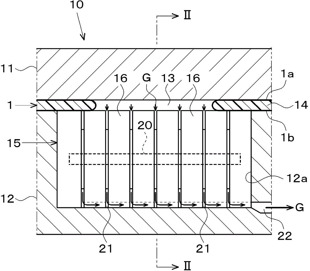
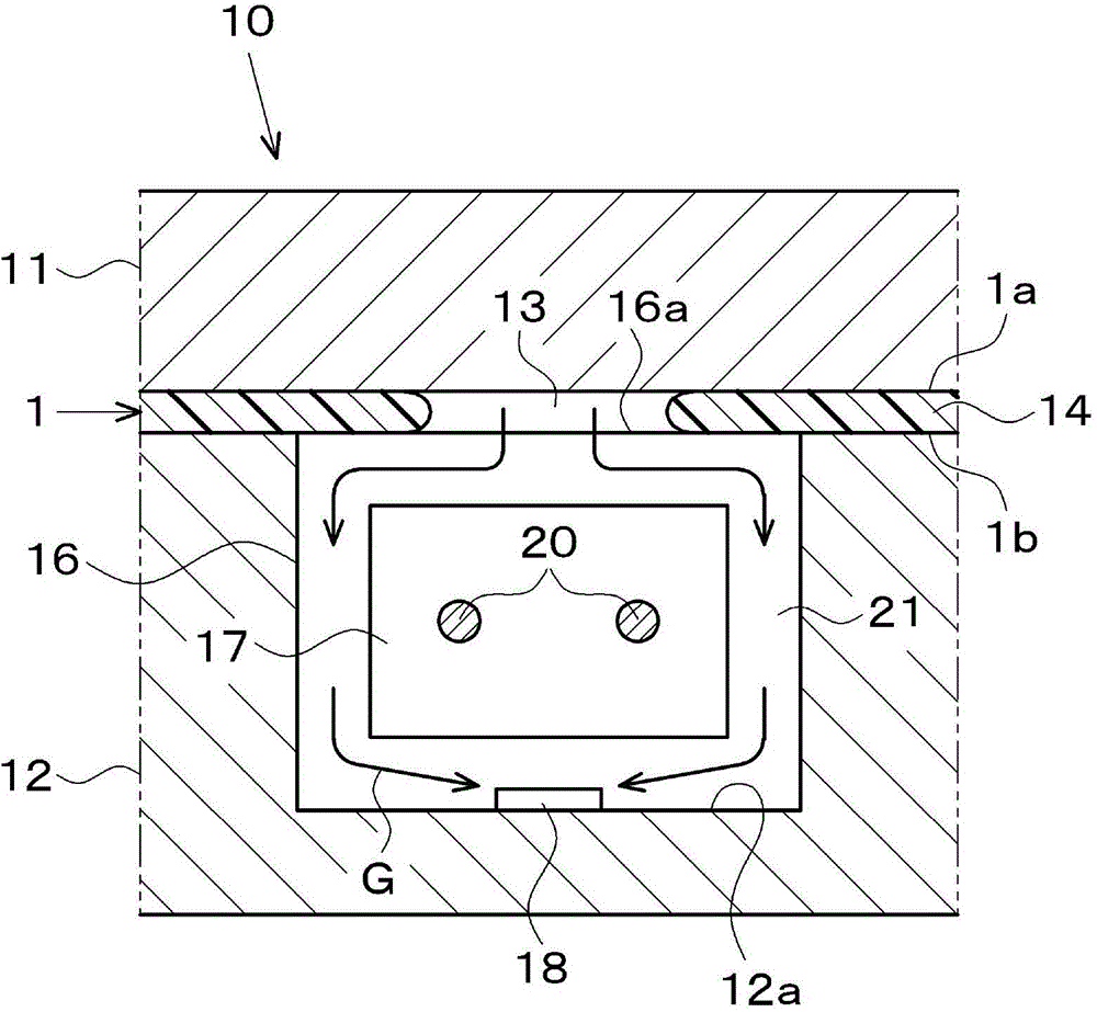
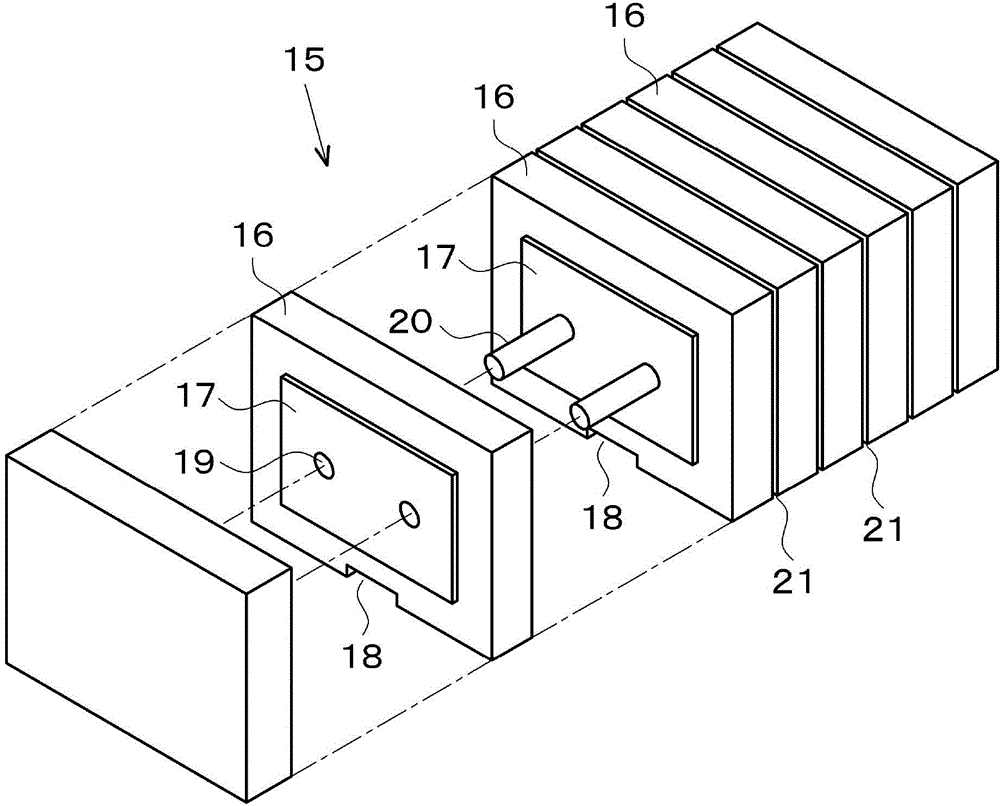
[0048] figure 1 , figure 2 The shown resin molding apparatus 10 includes a steel first mold 11 for molding the front surface 1 a of the resin molded product 1 , and a steel second mold 12 for molding the back surface 1 b of the resin molded product 1 . A cavity 13 is formed between the first mold 11 and the second mold 12 , and a concave portion 12 a is formed in the second mold 12 at a position corresponding to a meeting portion of the molten resin 14 injected into the cavity 13 . Also, an exhaust insert 15 is provided in the concave portion 12a, and the gas G (indicated by an arrow) remaining inside the chamber 13 is exhausted to the outside of the cha...


PUM

PropertyMeasurementUnit
heightaaaaaaaaaa

Abstract

The present invention relates to a resin forming device, a resin forming method, and a resin forming product for lamp fixtures. The resin forming device (10) comprises a first mold (11) used for forming the surface (1a) of a resin forming product (1), and a second mold (12) used for forming the back surface (1b) of the resin forming product (1). A chamber (13) is formed between the first mold (11) and the second mold (12). At a part corresponding to the resin assembly part of the chamber (13), an air-exhaust insert (15) is arranged at the second mold (12). The air-exhaust insert (15) is formed through multiple empiecements (16) configured to abut against one another. A gap (21) is formed between every two adjacent empiecements (16).

Description

technical field [0001] The present invention relates to a resin molding device provided with an exhaust insert, a molding method using the device, and a resin molded product for lamps formed using the device. Background technique [0002] When the aluminum vapor-deposited layer is directly formed on the exterior surface of the resin molded product for lamps and lanterns, since no primer is provided, the fusion marks on the exterior surface are easy to be conspicuous. E.g, Figure 7 As shown, in the resin molding device 53 using the steel molds 51 and 52, the molten resin 54 seals the gas in the meeting portion of the chamber 55, and the gas is sealed to generate dense fusion marks 56 on the surface and back of the resin molded product. Therefore, in the past, if Figure 8 As shown, the following resin molding device 59 is proposed: an insert 57 made of an air-permeable metal material is provided on the mold for back molding, so that the gas remaining in the cavity 55 leads ...

Claims


Application Information

Patent Timeline
Patent Type & Authority Applications(China)
IPC IPC(8): B29C45/34
CPCB29C45/34
Inventor 木幡隆宏池田利正饭田友范
Owner KOITO MFG CO LTD
Why Eureka
Try Eureka