Abandoned oil-gas pipeline grouting filling device and method

A technology for oil and gas pipelines and filling devices, which is used in soil protection, construction, infrastructure engineering, etc., and can solve the problems of inefficient and low-cost waste oil and gas pipeline grouting.

Inactive Publication Date: 2015-05-20
PETROCHINA CO LTD
View PDF5 Cites 10 Cited by
  • Summary
  • Abstract
  • Description
  • Claims
  • Application Information

AI Technical Summary

Problems solved by technology

[0005] Aiming at the problems existing in the prior art, the embodiment of the present invention provides a grouting filling device and method for an abandoned oil and gas pipeline, which is used to solve the technology in the prior art that cannot grout the abandoned oil and gas pipeline with high efficiency and low cost question

Method used


Image

  • Abandoned oil-gas pipeline grouting filling device and method
  • Abandoned oil-gas pipeline grouting filling device and method

Examples


Embodiment 1

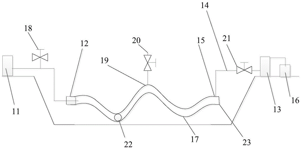
[0035] This embodiment provides a grouting filling device for abandoned oil and gas pipelines, such as figure 1 As shown, the device includes: a grouting machine 11, a grouting port 12, a sedimentation separator 13, a conduit 14, a grouting port 15 and a vacuum pump 16; wherein,

[0036] The grouting machine 11 is connected with the grouting port 12 at one end of the pipeline 17, and is used to inject the slurry into the pipeline 17 from the grouting port 12, and provide the forward power for the slurry to push the slurry. The body advances in the pipeline 17; wherein, the grouting port 12 is parallel to the axis of the pipeline 17 to convert the pressure of the grouting machine 11 into power. Wherein, the slurry is cement slurry, the amount of water reducing agent added to the slurry is 1.2%, and the water-cement ratio is 1:2.

[0037] One end of the sedimentation separator 13 is connected to the slurry outlet 15 at the upper end of the other end of the pipeline 17 through a...

Embodiment 2

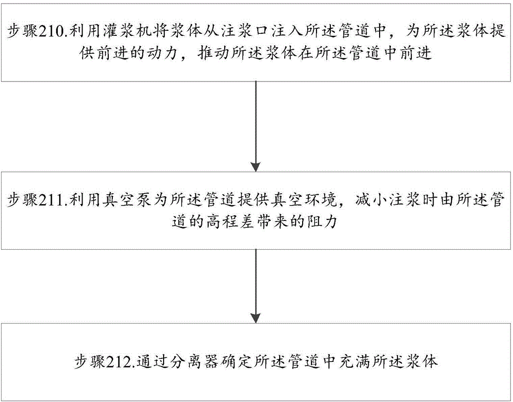
[0056] Corresponding to Embodiment 1, this embodiment provides a grouting filling method for abandoned oil and gas pipelines, such as figure 2 As shown, the method mainly includes the following steps:

[0057] Step 210, using a grouting machine to inject the slurry into the pipeline from the grouting port, and push the slurry forward in the pipeline;

[0058] In this step, the grouting machine is connected to the grouting port at one end of the pipeline, and the grouting machine is used to inject the prepared cement slurry into the pipeline, and provide forward power for the slurry to push the slurry in the Advance in the pipeline; close the second valve after a period of time to keep the pipeline airtight. Wherein, the grouting port is parallel to the axis of the pipeline, so as to convert the pressure of the grouting machine into power.

[0059] The switch state of the grouting port is controlled by the first valve.

[0060] Wherein, the position setting of the grouting ...


PUM


Abstract

The invention provides an abandoned oil-gas pipeline grouting filling device and a method. The abandoned oil-gas pipeline grouting filling device comprises a grouter, a sediment separator and a vacuum pump. The grouter is connected with a grout input arranged on one end of the pipeline, and is used for pouring the grout into the pipeline through the grout input and promoting the grout to advance in the pipeline; one end of the sediment separator is connected with a grout outlet arranged on the upper end of the other end of the pipeline, and is used for ensuring that the pipeline is filled with the grout; the vacuum pump is connected with the other end of the sediment separator, and is used for providing a vacuum environment for the pipeline during the grouting process and reducing the resistance caused by the elevation difference of the pipeline. The abandoned oil-gas pipeline grouting filling device and the method have the advantages that the grouting quality and grouting efficiency of the abandoned oil-gas pipeline with a long distance and a large caliber are guaranteed.

Description

technical field [0001] The invention belongs to the technical field of petroleum engineering, and in particular relates to a grouting filling device and method for waste oil and gas pipelines. Background technique [0002] The abandonment of oil and gas pipelines is an important part of pipeline life cycle management. When the service life of the pipeline reaches the upper limit or the benefits of continuing to transport oil and gas are far lower than the transportation cost, and the pipeline has no other potential uses, abandonment is an inevitable choice. [0003] Abandoned oil and gas pipelines generally have a long distance and a large diameter, and the terrain of the route is complex, and the altitude changes greatly. If passing through railways, highways, densely populated areas or other settlement-sensitive areas, the abandoned pipelines will eventually be fully corroded and lead to soil settlement, which will affect the stability of railways, highways and environment...

Claims


Application Information

Patent Timeline
Patent Type & Authority Applications(China)
IPC IPC(8): E02D15/04E02D3/12
CPCE02D15/04E02D3/12
Inventor 徐华天康叶伟郭正虹李志丹左莉王洪涛王禹钦张丰陈振华田小杰
Owner PETROCHINA CO LTD
Why Eureka
Try Eureka