
Brick falling machine for hollow brick leveling device

A hollow brick and brick dropping machine technology, which is applied in the processing of building materials, construction, building structure, etc., can solve the problems of large manual labor, considerable human and material resources, unfavorable engineering efficiency and safety, etc.

Active Publication Date: 2017-02-22
临沂恩科开发建设有限公司
View PDF6 Cites 0 Cited by
  • Summary
  • Abstract
  • Description
  • Claims
  • Application Information

AI Technical Summary

Problems solved by technology

[0003] In larger construction projects, such as the construction of community walls, walls are needed to divide the space. Due to the large amount of construction, the construction of such walls requires the cooperation of multiple people. Although the building form is simple, the cost The human and material resources are no less than the construction of buildings. In order to improve the construction efficiency of this type of wall, many wall building machines have come into people's sight. Most of the wall building machines in the prior art use manual work to arrange the bricks into an orderly one. row, and then put them in the bricks dedicated to the wall machine. However, the amount of manual labor is still huge, which is not conducive to the improvement of engineering efficiency and the safety of personnel. In order to improve the artificial working environment, people began to use automatic bricks. However, this type of device requires bricks to be put in one by one, otherwise the bricks will be stacked, and the device that arranges the bricks neatly will not work. In order to further improve the automation of this type of device, people need a A device that replaces manual placement of bricks and is used in conjunction with a device for neatly arranging bricks, and can place bricks one by one into a turning device

Method used


Image

  • Brick falling machine for hollow brick leveling device
  • Brick falling machine for hollow brick leveling device
  • Brick falling machine for hollow brick leveling device

Examples


Embodiment Construction

[0017] In order to make the technical means, creative features, goals and effects achieved by the present invention easy to understand, the present invention will be further described below in conjunction with specific illustrations.

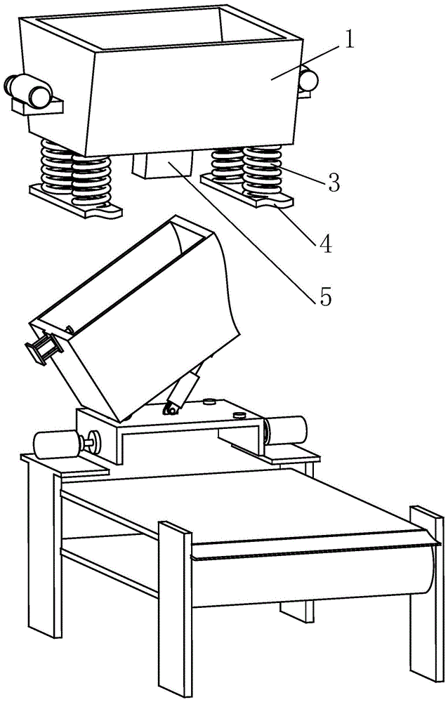
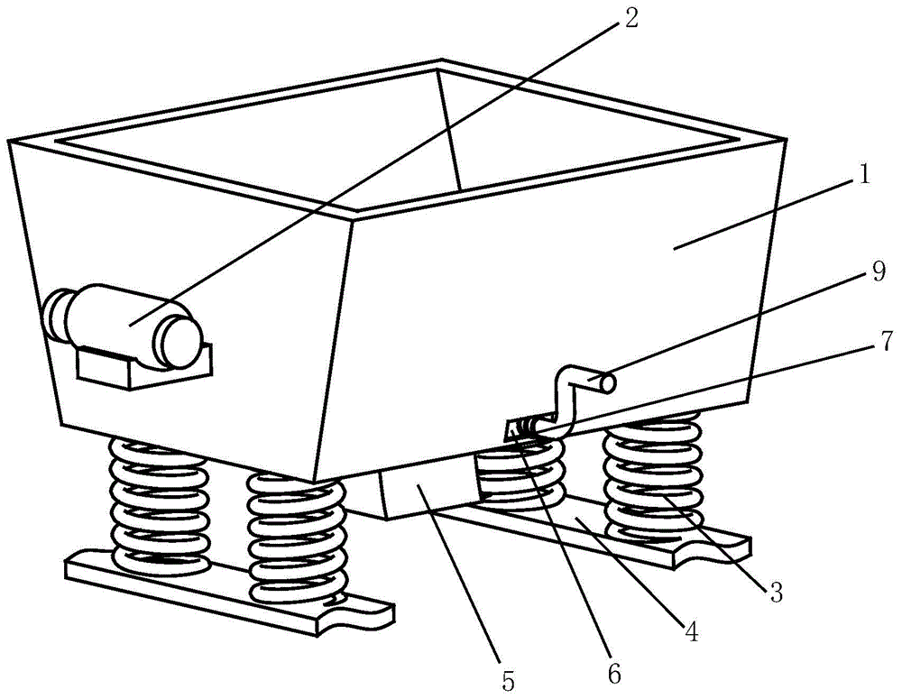
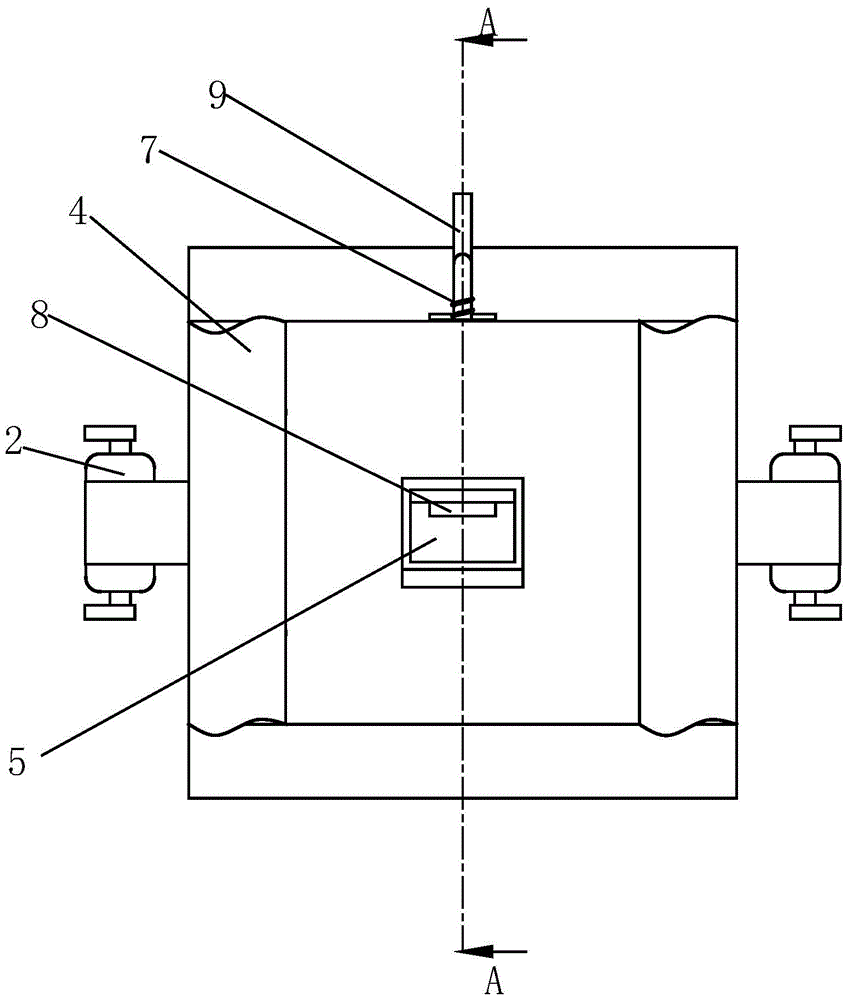
[0018] Such as Figure 1 to Figure 4 As shown, a brick falling machine for a hollow brick leveling device includes a box body 1, the box body 1 is a truncated cone shape, so that the bricks are automatically concentrated in the middle of the box body 1, and the left and right sides of the box body 1 are respectively equipped with There is a vibrating motor 2, and the two vibrating motors 2 are left-right symmetrical about the median plane of the box body 1, and the rotation directions of the two vibrating motors 2 are opposite. When the above-mentioned two vibrating motors 2 rotate at the same time, the two are mutually balanced , the left and right sides of the lower end surface of the box body 1 are provided with shock absorbing springs 3, the...


PUM


Abstract

The invention relates to a brick dropping machine for a hollow brick flatly placing device. The brick dropping machine for the hollow brick flatly placing device comprises a box body, wherein the left side and the right side of the box body are each provided with a vibration motor; the left side and right side of the lower end surface of the box body are each provided with a damping spring; the lower ends of the damping springs are each provided with a support board; the middle portion of the bottom surface of the box body is provided with a brick flowing channel; the front side of the bottom of the box body is provided with a longitudinal front through hole, the front end of the front through hole extends to the front end surface of the box body, and the rear end of the front through hole extends to the inner wall of the brick flowing channel; a threaded rod is matched in the front through hole in a threaded connection mode; the rear portion of the front through hole is also provided with a hole covering board capable of sliding along the front through hole; the front end surface of the hole covering board is fixedly connected with the rear end surface of the threaded rod; the front end of the threaded rod is provided with a rotary handle. According to the brick dropping machine for the hollow brick flatly placing device, bricks are output from the box body in a single and continuous delivery state, and the placing states of the output bricks are consistent with each other; manpower is replaced in the brick arrangement and the brick putting in the device capable of tidily placing the bricks, and the labor cost and the equipment usage amount are reduced.

Description

technical field [0001] The invention relates to the technical field of construction equipment, in particular to a brick dropping machine for a hollow brick leveling device. Background technique [0002] In architecture, a wall refers to a space partition structure, which is used to enclose, divide or protect a certain area, and is one of the most important elements in architectural design. [0003] In larger construction projects, such as the construction of community walls, walls are needed to divide the space. Due to the large amount of construction, the construction of such walls requires the cooperation of multiple people. Although the building form is simple, the cost The human and material resources are no less than the construction of buildings. In order to improve the construction efficiency of this type of wall, many wall building machines have come into people's sight. Most of the wall building machines in the prior art use manual work to arrange the bricks into an...

Claims


Application Information

Patent Timeline
IPC IPC(8): E04G21/22
Inventor 胡玉平
Owner 临沂恩科开发建设有限公司
Learn More