Method for detecting an error in the opening behavior of an injector

A technology for opening characteristics and injectors, which is applied to fuel injection devices, fuel injection control, machines/engines, etc., and can solve the problems of expensive opening delay, cumbersome, and cannot be easily implemented.

Active Publication Date: 2015-05-20
ROBERT BOSCH GMBH
View PDF6 Cites 0 Cited by
  • Summary
  • Abstract
  • Description
  • Claims
  • Application Information

AI Technical Summary

Problems solved by technology

However, determining the opening delay, for example according to document DE 10 2009 028 650 A1, is very expensive and cumbersome and cannot easily be implemented in the operation of the internal combustion engine

Method used


Image

  • Method for detecting an error in the opening behavior of an injector
  • Method for detecting an error in the opening behavior of an injector
  • Method for detecting an error in the opening behavior of an injector

Examples


Embodiment Construction

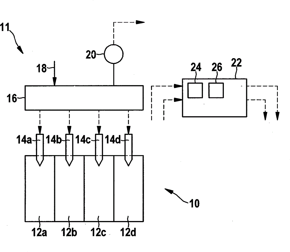
[0035] figure 1 A simplified schematic diagram of a fuel system 11 of an internal combustion engine 10 with four existing cylinders 12 and associated injectors (or injection valves) 14 for injecting fuel that are electronically controlled, the solenoid The injectors are associated with the cylinders of the internal combustion engine 10 with identifications a to d, but for general reference no identification is given below. In this particular embodiment, the injector 14 constitutes an electromagnetically controlled electromagnetic injector. However, the injector 14 can also be formed, for example, as a piezoelectric injector. Each electromagnetic injector 14 has one (in figure 1 not visible in ) solenoid-operated valve element 15 (see figure 2 ). A common rail block 16 is shown above the electromagnetic injector 14 , which is supplied with fuel by a high-pressure line 18 and monitored by a pressure sensor 20 . Internal combustion engine 10 is designed either as an Otto en...


PUM


Abstract

A method for detecting an error in the opening behavior of an injector of an internal combustion engine, the injector having an electromagnetically actuated valve element, a ballistic partial injection being carried out, the injector being ballistically activated, so that the valve element is not opened up to a lift stop, a ballistic closing delay period is determined, the determined ballistic closing delay period is compared with a reference value, and an error in the opening behavior of the injector is detected with the aid of the comparison.

Description

technical field [0001] The invention relates to a method for detecting faults in the opening behavior of an injector. Background technique [0002] Injectors are well known and used in many ways, especially as fuel injectors in internal combustion engines. Electromagnetic injectors and piezoelectric injectors are promoted. A typical injector includes an electrically controllable valve element capable of opening and closing a fuel flow path. The valve element comprises a needle valve (or injector needle valve) and a solenoid actuator (armature or magnetic armature and coil) or a piezoelectric actuator. The actuator is coupled to the needle valve and is electronically controlled. The actuator and the needle valve are pressed into the dead-end end ("standard position", "zero position") by the valve spring. In this non-operating terminal, the fuel flow path is either closed (NC) or open (NO). [0003] In electromagnetic injectors, an electromagnetic force is generated by ac...

Claims


Application Information

Patent Timeline
Patent Type & Authority Applications(China)
IPC IPC(8): F02D41/22F02D41/30
CPCF02D41/221F02M51/06F02D41/2438F02D41/2467F02D41/247F02D2041/2051F02M45/04F02M51/0603F02M65/005Y02T10/40F02M51/00F02M65/00
Inventor M. 威利莫夫斯基M. 安勒A. 申克楚施魏因斯贝格F. 施蒂夫K. 约斯
Owner ROBERT BOSCH GMBH
Why Eureka
Try Eureka