[0065] In conventional traction controls and control methods, an ATCM, such as ATCM 45, sends TSC1 messages to an ECM, such as ECM 23. In accordance with current industry practice, it is preferred that the TSC1 messages from ATCM are addressed to ECM. The ECM is adapted to monitor a controller
bus for the presence of TSC1 messages and implement control of engine 14 in response thereto using known methods. In accordance with conventional industry practice and hardware, the TSC1110 messages from ATCM are sent with the Override
Control Mode parameter set to “Speed / Torque Limit Control”. This setting of the Override
Control Mode parameter is a torque
limit setting of this parameter, and is adapted to limit the output torque of the engine to a percentage of a fixed reference engine torque (typically a maximum engine output torque), rather than an actual torque command value, as described in SAE J1939. While the TSC1 messages with the Override
Control Mode parameter set to Speed / Torque Limit Control are well adapted and widely used to control vehicle powertrain systems comprising an
internal combustion engine and transmission, the conventional use of SAE J1939 traction control hardware,
software and message parameters is not suitable to directly provide traction control of a vehicle powertrain system of a hybrid
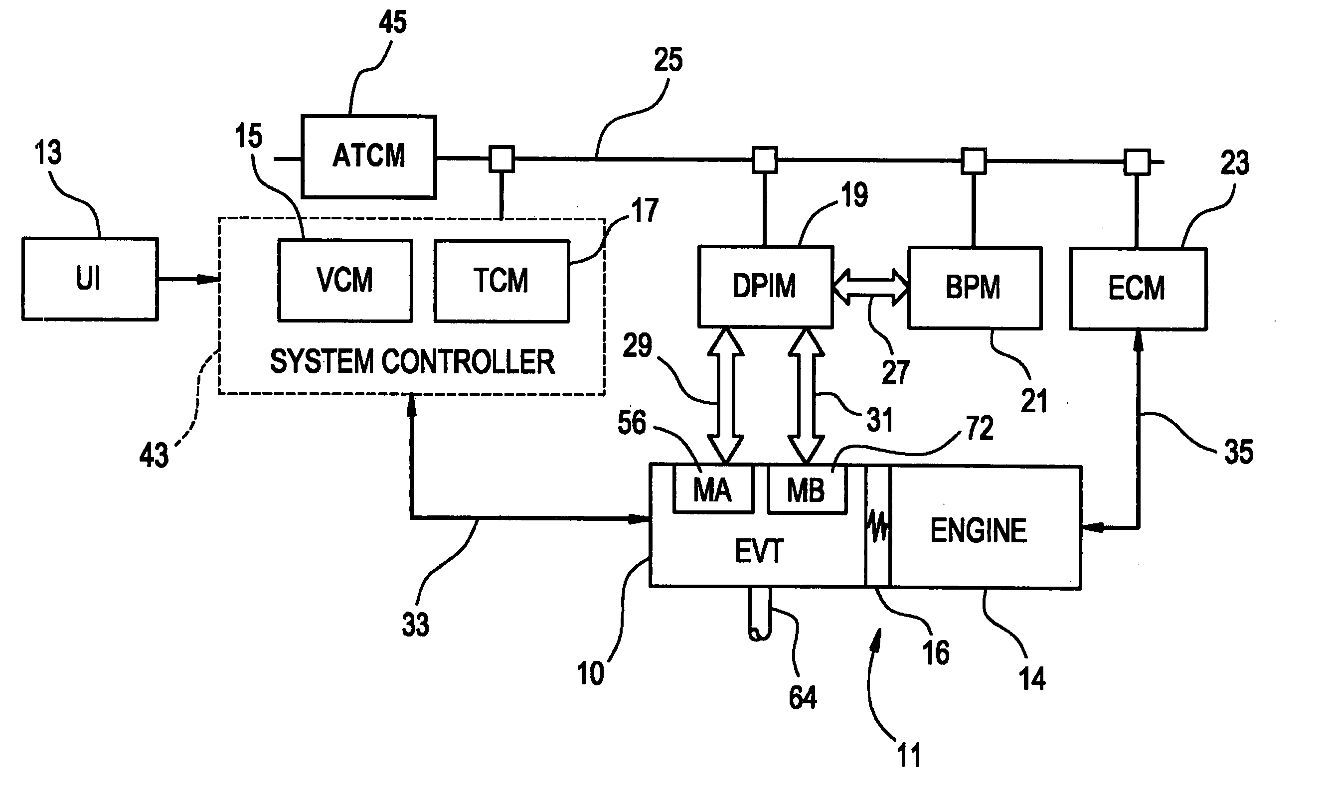
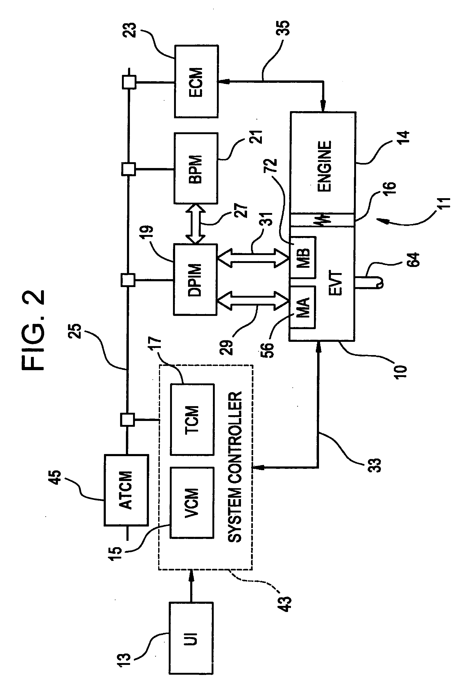
electric vehicle, such as vehicle powertrain system 11. This is because the vehicle powertrain system of a hybrid electric vehicle, such as vehicle powertrain system 11, has additional inputs for controlling the output torque of the transmission that must be controlled in addition to an
internal combustion engine, such as engine 14, namely, an electric
machine or plurality of machines, such as is MA 56 and MB 72, as described herein, that are not adapted for control by the conventional implementation and use of TSC1 messages. Further, the fact that conventional commercial hardware is adapted to send TSC1 messages with the Override Control Mode parameter set to Speed / Torque Limit Control is undesirable even for
direct control of the engine in a hybrid electric vehicle, because in order to optimize system performance it is typically desirable to command the engine to a particular engine output torque, Te, as described herein, rather than to a torque
limit value. However, method 100 is adapted to utilize conventional commercial hardware for the ATCM and ECM, such as ATCM 45 and ECM 23, and a conventional
communications protocol, such as the SAE J1939 protocol, as well as the conventional TSC1 messages available from the traction control with the Override Control Mode set to Speed / Torque Limit Control, and yet also fully utilize the torque output control flexibility of the hybrid electric vehicle to provide traction control for vehicle powertrain system 200, which includes an engine, an electric
machine or machines and an EVT, as further described herein. This use of conventional traction control hardware and
software noted above in conjunction with the implementation of method 100 in a vehicle powertrain system 200 is a particular
advantage of the present invention.
[0066] Referring again to FIGS. 5, 7 and 8, in conjunction with the step of sending 120 first output torque command messages 210 to second controller 215, second controller 215 monitors controller
bus 220 to detect the presence of first output torque command messages 210. This monitoring of the controller
bus to detect the presence of first output torque command messages 210 may be performed using known hardware, software and control algorithms, such as those normally implemented in an engine controller, such as ECM 23. For example, monitoring of messages may be performed using a persistent counter which is adapted to determine the presence of one or more messages. Also, in conjunction with the step of sending 120 the plurality of first output torque command messages 210 to second controller 215, second controller 215 is adapted to receive, store and process each of the plurality of first output torque command messages 210 using well-known hardware and software for receiving, storing and
processing such messages, as illustrated by block 300 of FIG. 8. As described above, second controller 200, such as
system controller 43, is also adapted to continuously determine To_des 225 in conjunction with control loops executed by the
system controller 215, as described herein, and as illustrated by block 310 of FIG. 8.
[0067] Referring now to FIGS. 5, 7 and 8, method 100 also includes a step of determining 130 a reference output torque (To_ref) 230. To_ref 230 may be any reference output torque that is suitable for use in conjunction with the remainder of the steps of method 100 for determining a plurality of traction control output torque commands. However, it is preferred that To_ref comprise the To_des of the vehicle powertrain system, such as vehicle powertrain system 11, at a time, to, corresponding to the
receipt of the first one of the plurality of first output torque command messages (To_des (to) 226), which corresponds to the onset of the wheel spin condition, as illustrated in FIGS. 9 and 10. If To_des is constrained as described herein, it is further preferred that To_ref comprise the constrained value or command associated with To_des. This is illustrated symbolically in block 320 of FIG. 8 by latching the value of To_des 225 that is provided continuously by
system controller 215 at To_des(to) 226 by moving the switch shown in block 330 from position 1 to position 2 at time to to store a value for To_des(to) 226. This representation is only symbolic in nature for the purpose of illustration, and not representative of hardwired logic lines. The value of To_des(to) 226 is preferably stored in memory as a reference value by a computer in second controller 215. The reason for and advantages associated with this preference regarding the value of To_ref may be understood by contrasting the present invention with a conventional implementation of an automatic traction controller. In a conventional implementation of an automatic traction controller in a vehicle powertrain system consisting of an internal
combustion engine and transmission, as has been described herein, the plurality of TSC 1 messages each contain a torque limit or torque reduction percentage identified in their respective torque command parameters. In such implementations, a TSC1 message is received by the engine controller and the respective torque reduction is applied to a fixed reference engine torque that is typically determined from a maximum engine output torque. In the present invention, To_ref is preferably determined to be the value of To_des at the onset of the wheel spin condition. To_ref is not only a more representative reference of the torque output of the vehicle powertrain system at the onset of the wheel spin condition, and thus a better basis against which to apply subsequent control actions, but the To_des associated with To_ref also has associated therewith operating points for both the engine and the electric machine or machines, such as Te, Ta and Tb in the case of vehicle powertrain system 11. As the control actions are applied to reduce To_des, effectively determining a new or override value of To_des associated with the wheel spin condition, new values for Te, Ta and Th can also be determined in the manner described herein.
[0068] It is further preferred that the value of To_ref be limited to values that are greater than a predetermined minimum reference output torque limit 227 (To_ref_limit). Therefore, it is preferred that the step of determining 130 To_ref further comprises a step of selecting the reference output torque from the greater of To_des(to) 226 and To_ref_limit 227. It is further preferred that To_ref_limit 227 be established as a value that is greater than zero, and that this value be dependent on the nature of the vehicle, such as for example, a value of about 678 n-m for vehicle 10.
[0069] Referring to FIGS. 5-8, method 100 also includes a step of determining 140 a plurality of traction control output torque commands 235 corresponding to the plurality of first output torque command messages 210 as a function of To_ref 230. Referring to FIG. 6A, this step of determining 140 may be accomplished for each traction control output command by the further steps of determining 142 an output torque reduction 245 from the corresponding first output torque command message 210; and applying 144 the output torque reduction 245 to the reference output torque 230 to determine the traction control output torque command 235. This step is illustrated in block 330 of FIG. 8. In block 330, the switch shown therein is a symbolic representation, wherein position 2 of the switch is representative of a traction control operational state of second controller 215 wherein the traction control and method 100 is active and traction control output torque command is the commanded To of vehicle powertrain system 200. In this state, wherein the traction control is active, the normal operating state represented by switch position 1, wherein To_des 225 is the commanded To of vehicle powertrain system 200, is temporarily overridden for a time period corresponding to the duration of the wheel spin condition. This transition from the normal operating state to the activation of the traction control operating state is also illustrated in FIGS. 9 and 10. It will be understood by those of ordinary skill that the change in operational state represented by the switch in block 330 may correspond to any suitable means of adapting second controller 215 to switch the basis of control from To_des to To_trac_cmd, including means utilizing hardware, software or combinations thereof. It is preferred that this change in the operational state be implemented using a
computer control algorithm that is triggered by the
receipt of the first output torque command messages by second controller 215 as illustrated and described herein regarding block 300. Such means are well known.
[0070] In the case where first output torque command messages 210 comprise TSC1 messages in accordance with SAE J1939-71, as described herein, determining 142 the output torque reduction 245 comprises obtaining output torque reduction 245 from the Override Control Mode parameter of each of the TSC1 messages 210 from the
limit value included therein in accordance with SAE J1939 when this parameter is set to Speed / Torque Limit Control, as described above. As noted above, TSC1 messages from a conventional ATCM, such as ATCM 45, typically set the Override Control Mode parameter to “Speed / Torque Limit Control” and then, in accordance with J1939-71, set the torque limit as a
percentage reduction of output torque which is to be applied against a reference output torque value. Output torque reduction 245 may be obtained from the first output torque command messages 210 using known methods. The step of applying 144 the output torque reduction 245 to To_ref 230 to determine the To_trac_cmd 235 may then simply comprise multiplying the
percentage reduction by To_ref 230 to obtain To_trac_cmd 235. Thus, for each of first output torque command messages 210 a corresponding To_trac_cmd 235 may be determined. Since ATCM 45 is adapted to remain active and transmit first torque command messages 210 messages in accordance with SAE J1939 for the duration of a wheel spin condition, which corresponds to the time interval from time to to time tF as shown in FIGS. 9 and 10, method 100 is adapted to provide a corresponding plurality of reduced traction control output torque commands 235 for the duration of the wheel spin condition, as illustrated in FIGS. 8-10.

