Thermal management systems and methods

a technology of management system and thermal management system, applied in the direction of machine/engine, battery/fuel cell control arrangement, light and heating apparatus, etc., can solve the problems of reduced battery performance, less reliable hevs in northern latitudes, and unbalanced electrical modules, etc., to increase sensible heat or latent heat of fusion

Inactive Publication Date: 2006-12-12
BATTELLE ENERGY ALLIANCE LLC
View PDF29 Cites 180 Cited by
  • Summary
  • Abstract
  • Description
  • Claims
  • Application Information

AI Technical Summary

Benefits of technology

[0010]In yet other embodiments, a thermal management method for a vehicle includes providing a heat exchanger having a thermal energy storage material disposed therein, providing first and second coolant loops to circulate distinct coolant mixtures through the respective first and second coolant loops, thermally coupling the first coolant loop to a battery module located within the first coolant loop, thermally coupling the second coolant loop to the heat exchanger, and providing an interface in close proximity to the second coolant loop. The interface is configured to transfer heat generated by an internal combustion engine of the vehicle to the heat exchanger, via the second coolant loop, for storage within the thermal energy storage material. The method also includes selectively performing one or more of preheating the battery module, heating a passenger cabin of the vehicle, increasing sensible heat or latent heat of fusion of the material from a first thermal state to a higher second thermal state using the heat stored within the thermal energy storage material.

Problems solved by technology

Such varied charge-discharge behavior may lead to electrically unbalanced modules and reduced battery performance.
HEVs may be less reliable in northern latitudes due to cold temperature constraints imposed on the batteries carried by the HEVs.
Conversely, as temperatures exceed above 40° C., detrimental cathode corrosion and other irreversible reactions may occur resulting in shortened battery life.

Method used


Image

  • Thermal management systems and methods
  • Thermal management systems and methods
  • Thermal management systems and methods

Examples


Embodiment Construction

[0018]This disclosure of the invention is submitted in furtherance of the constitutional purposes of the U.S. Patent Laws “to promote the progress of science and useful arts” (Article 1, Section 8).

[0019]The following terminology as described below is used to define terms that are used in this application.

[0020]The following operational parameters and control strategy may be used in various embodiments:

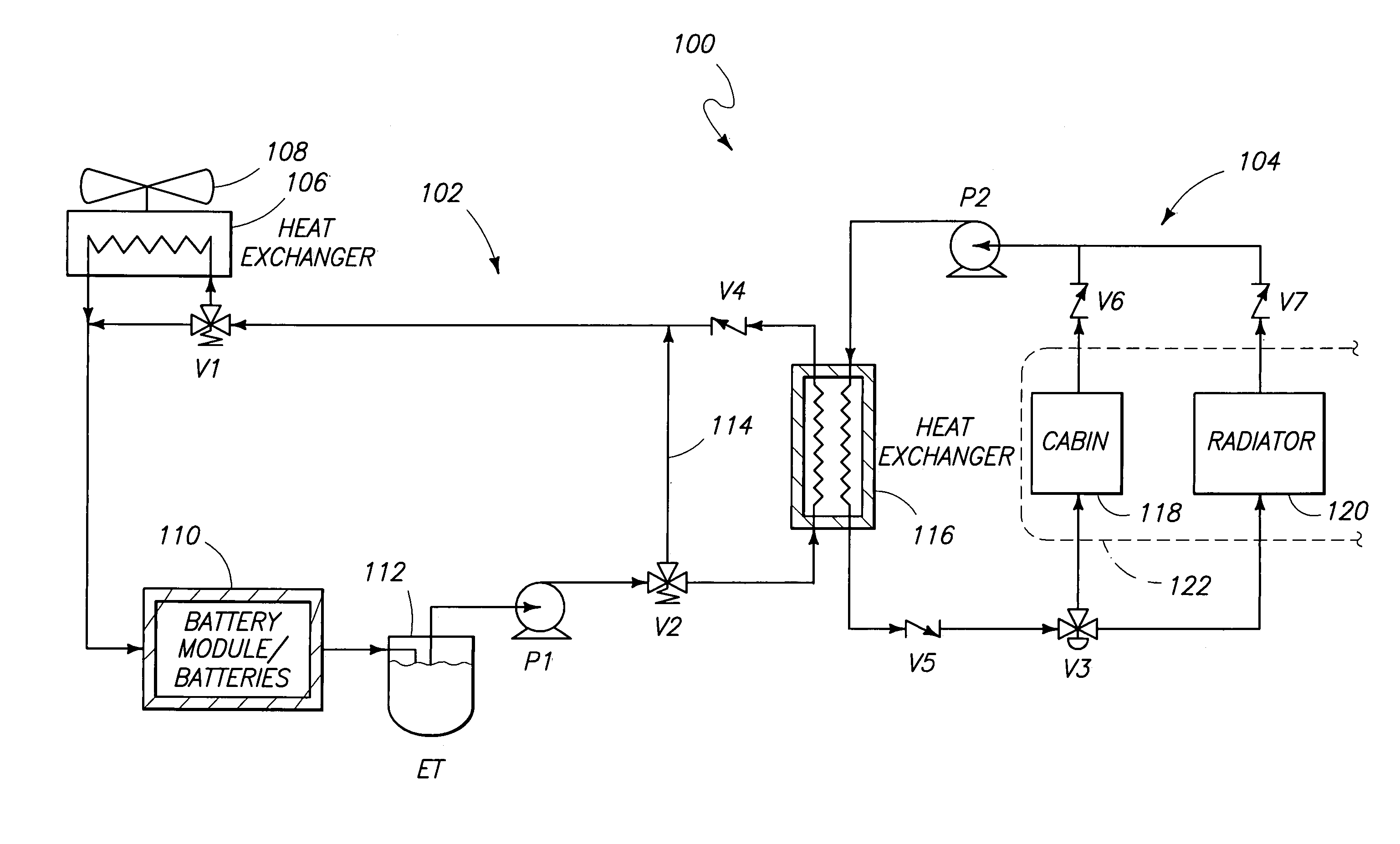
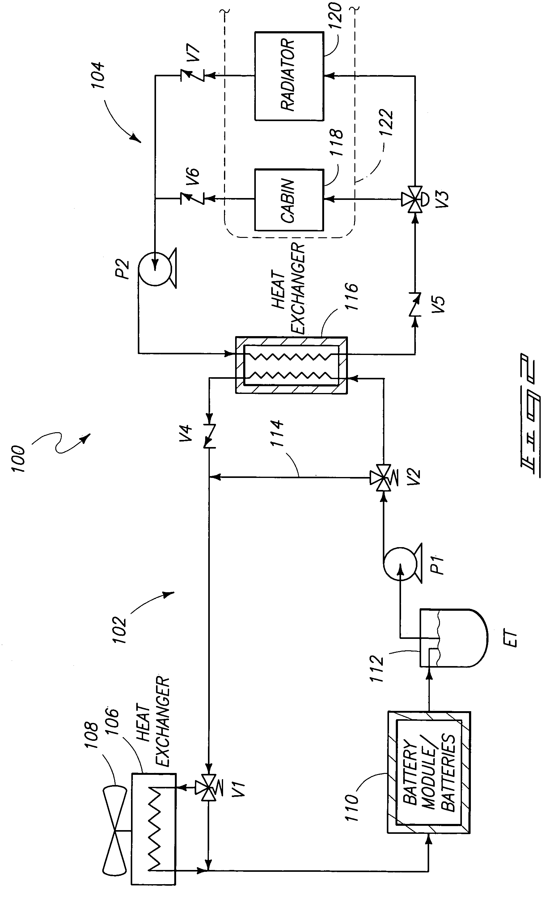
[0021]Measured Temperatures.[0022]TBatt: average or representative temperature within battery module of battery 110.[0023]TCab: representative temperature of coolant within the internal combustion engine cabin (ICE cabin) heater core 118.[0024]TPCM: average or representative temperature within phase change material (PCM) module 214, 218 of heat exchanger (HX) 116.[0025]TRad: representative temperature of the internal combustion engine radiator coolant / fluid in loop 104.

[0026]Set-Point Temperatures.[0027]Tmin: minimum desirable battery temperature.[0028]Tmax: maximum desirable battery ...


PUM


Abstract

A thermal management system for a vehicle includes a heat exchanger having a thermal energy storage material provided therein, a first coolant loop thermally coupled to an electrochemical storage device located within the first coolant loop and to the heat exchanger, and a second coolant loop thermally coupled to the heat exchanger. The first and second coolant loops are configured to carry distinct thermal energy transfer media. The thermal management system also includes an interface configured to facilitate transfer of heat generated by an internal combustion engine to the heat exchanger via the second coolant loop in order to selectively deliver the heat to the electrochemical storage device. Thermal management methods are also provided.

Description

GOVERNMENT RIGHTS[0001]This invention was made with Government support under Contract No. DE-AC07-99ID13727 awarded by the U.S. Department of Energy. The Government has certain rights in the invention.TECHNICAL FIELD[0002]Aspects of the invention generally relate to thermal management systems (TMSs) and methods.BACKGROUND OF THE INVENTION[0003]Hybrid electric vehicles (HEVs) and electric vehicles (EVs) provide improved fuel economy and reduced air emissions over conventional vehicles. The performance of HEVs and EVs depend on energy storage systems such as batteries. Battery performance influences, for example, acceleration, fuel economy, and charge acceptance during recovery from regenerative braking. As the cost of the batteries, durability, and life-cycle affect the cost and reliability of a vehicle using the batteries for vehicular operation, parameters that affect the efficiency of the batteries may have to be optimized to achieve optimized vehicular performance.[0004]It is kno...

Claims


Application Information

Patent Timeline
Patent Type & Authority Patents(United States)
IPC IPC(8): B60K1/00B60H1/00B60K11/02F01P3/20F01P7/16F01P11/20
CPCB60H1/00278B60H1/004B60H1/00492B60H1/08B60K11/02B60L11/12B60L11/1874B60L11/1875F01P3/20F01P11/20B60H2001/00307B60K2001/005F01P7/165F01P2011/205F01P2050/24F01P2060/08F01P2060/18Y02T10/7077Y02T10/7005Y02T10/705B60L50/15B60L58/26B60L58/27Y02T10/70Y02T10/7072
Inventor GERING, KEVIN L.HAEFNER, DARYL R.
Owner BATTELLE ENERGY ALLIANCE LLC
Why Eureka
Try Eureka